How to define new Storeys
Introduction to Storeys
Storeys is a special entity in SCIA Engineer. It is defined by “Storey manager” dialogue. The Storeys object can be only once in the project. Any changes can be done in “Storey manager”.
Storeys can be used with 2D linegrid. Together they create similar object as 3D linegrid. A visual copy of a 2D linegrid in each Storey is controlled by view parameters.
Location of Storeys in SCIA Engineer
Storeys dialogue can be started from service “Line grid and storeys”.

Dialogue “Storey manager” starts. Each storey can be defined in an ordinary grid.

How to define Storeys
- Open a new blank project in SCIA Engineer with this settings:
- Structure – General XYZ
- Project level – Advanced
- Model – One
- Material – Concrete
- National code and annex – EN
No more functionality is needed for the Storeys input.

- Find the command Storeys and start dialogue Storey manager.

- Define a new name for floors. Write down “Floor” in the column for the name. It is automatically renamed to “Floor1”.
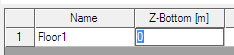
- Define “Z-bottom” to -2.000m and “h_fl” to 4.500m. “Rep” stays 1.

There is a scheme of Storeys in the picture above. One storey is defined.
- Define another row = next level with these settings:
“h_fl” = 3.000
“Rep” = 2
“Description” = Second level

The preview is automatically updated according to the changes in the dialogue.
- Add 2 more levels with height 2.000 and 5.000m.


Modification of Storeys
- Storeys can be edited only in the “Storey dialogue”. Start this dialogue again.
- Buttons “Insert” and “Delete” modify the number of rows in the dialogue. Click on row number 3 and then on the “Insert” button.

There is a new row with default values from row number 4.

- Click on the row with number 6 and push button “Delete”.
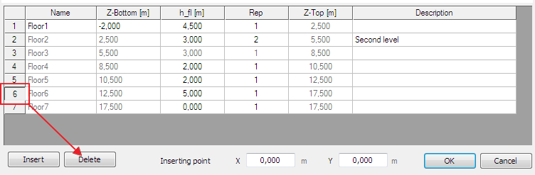
The 6th row is deleted from the grid.

- Edit value for “Z-bottom” from -2.000 to -0.500. All values under this cell are automatically recalculated.

- Edit value “Rep” in 4th row from 1 to 3.

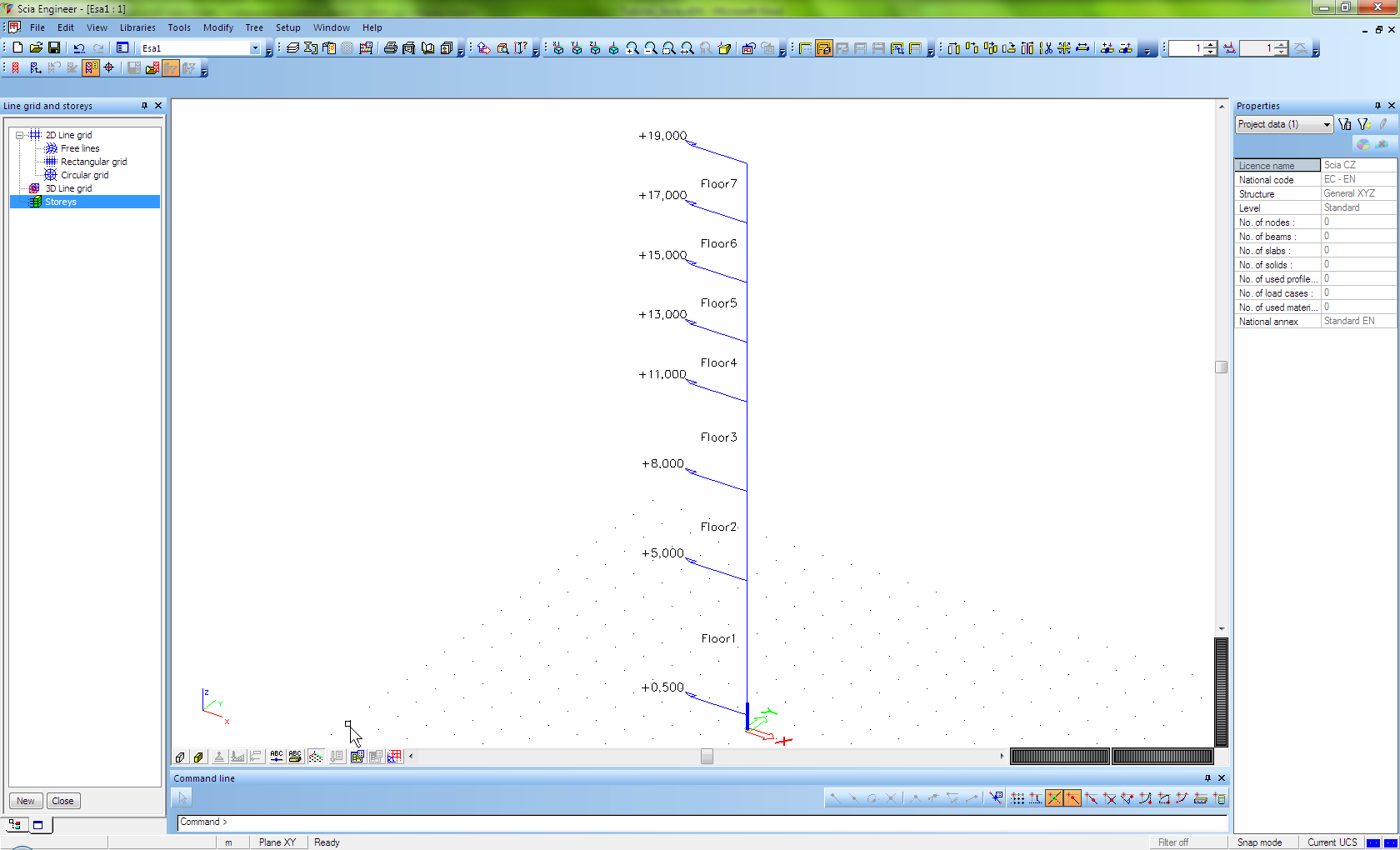
- See the result in the 3D window.
- Result is also saved in project “storeys_final.esa”.
Storeys and Linegrid in one project.
- Open project “storeys+linegrid_start.esa”.

- Open service “Line grid and storeys”.

- Define Storeys with these settings:
“h_fl” in 1st row = 3, “Rep” = 2
“h_fl” in 3rd row = 2, “Rep” = 1
Inserting point is x=-5.000, y=-2.000


- Close “Line grid and Storeys” service and see the changes in the 3D model. The 2D linegrid is copied to the each level of Storeys.

- Change view parameters for the whole structure. Tab “Modelling/Drawing”, item “Grid projection” -> uncheck the checkbox and confirm it by OK button.

The 2D linegrid is displayed only in the working plane.

- The result is in file “storeys+linegrid_final.esa”.
How to use storey activity
- Open file “storeys+linegrid_final.esa”.
- Graphically select all three storeys in the project and set their properties to “Include members on top” and “Include members on bottom” as checked. Then click action button “Allocate automatically”.

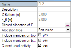
- Deselect all storeys and now select only the second level. Set property “Allocation type” to Part inside. Click action button “Allocate automatically”.
- Use View Y.
- Switch activity to Activity by storey. Confirm the warning.

- The new dialogue is opened. All possible activities that can be used for storeys are here.
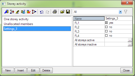
- Select “One storey activity” and there only 1st level – FL1. Close the dialogue.

The result in the 3D window:

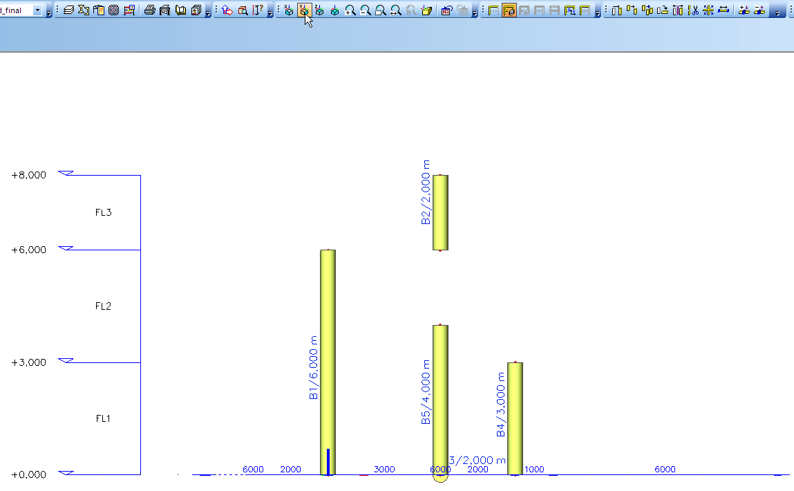
- Go again to the “Storey activity” dialogue and select Settings_3. Check also the second storey – FL2. Close the dialogue.

The result in the 3D window:

- Conclusion: The activity by storeys works in the similar way as activity by Layers. It is useful functionality for higher buildings. The engineer has possibility to work in separate levels without defining layers.