FEM - connecting of FE nodes
Introduction
This chapter is to provide a closer information about certain features of connecting of finite element nodes.
Connecting of finite element nodes
Below, examples of finite element model behaviour are provided. In certain cases, in a place where two coincident finite element nodes would need to be created, one finite element node is generated, what causes rigid connection of the structural model in that area. For example, under a single force acting on beam, a finite element node is created, and if there is a second beam that would have a finite element node in that exact position, these nodes are coincidently considered as only one (see case #C)
Examples
Case #A = 2 beams crossing each other = there is no finite element node in the area of crossing at all due to mesh setting. No connection of members.


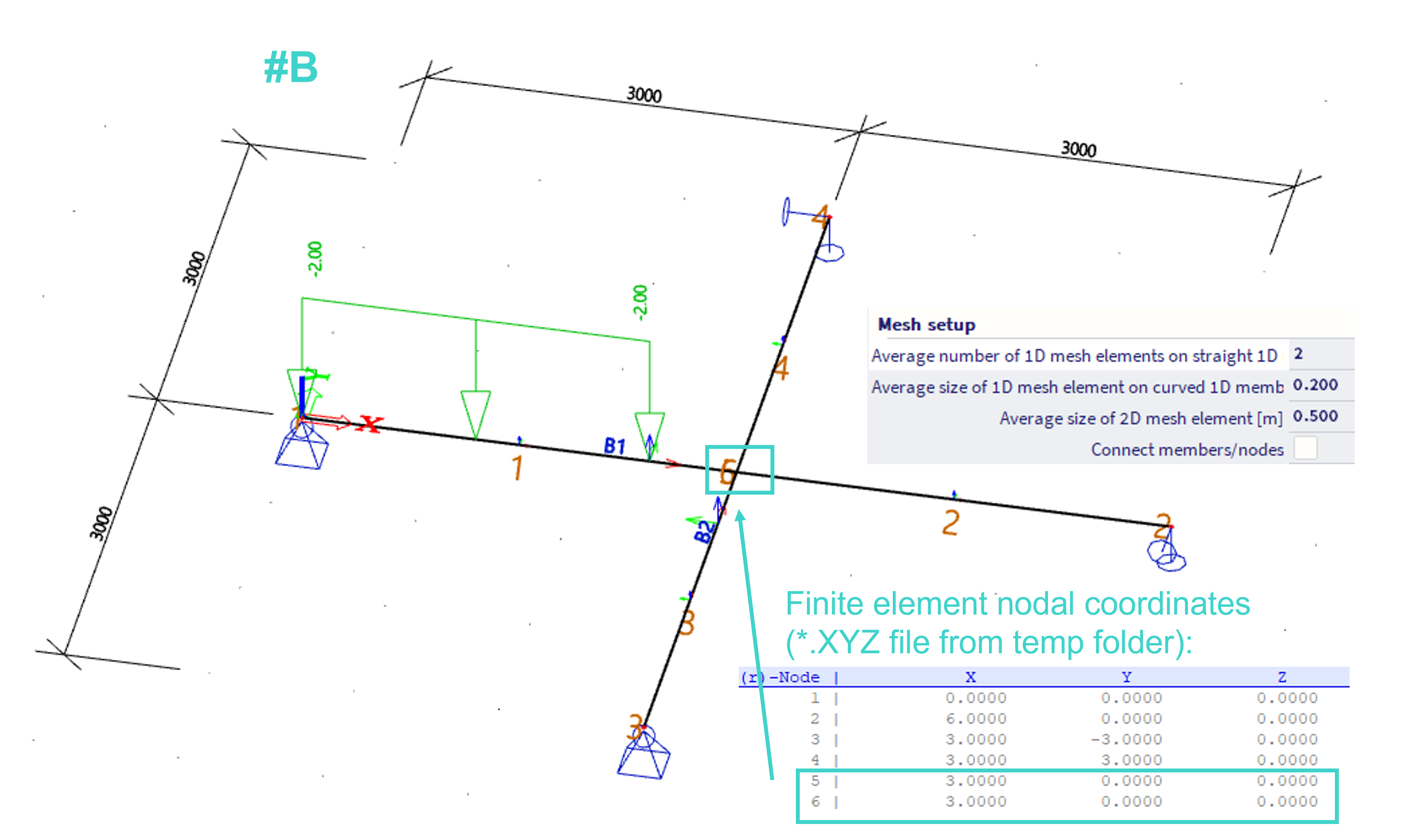
Case #B = 2 beams crossing each other = there are 2 coincident finite element nodes in the area of crossing. No connection of members.

Case #C = 2 beams crossing each other, and one is loaded by a single force exactly in the mid span. In this case, there is finite element node generated underneath this force and the beams are rigidly connected (also when the "connect members / nodes" within the mesh setup is turned off). In order not to connect these two beams together, there needs to be only one 1D finite element on the second beam (mesh setup), or, the force needs to be shifted a little (e.g. 0.1 mm to the right).


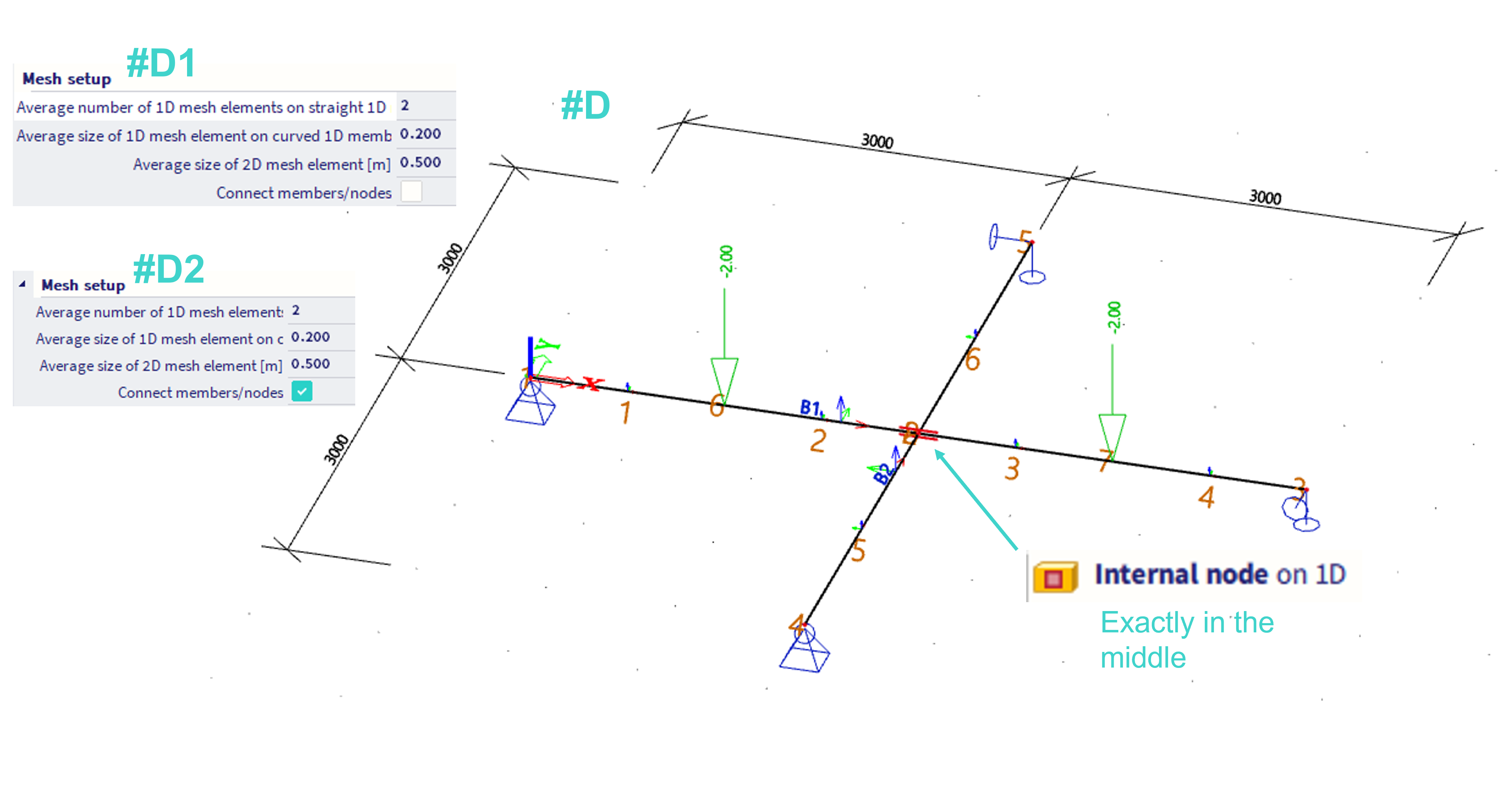
Case #D = 2 beams crossing each other, and there is an internal node defined on one of these beams (exactly in the middle). no matter whether the "connect members / nodes" is on (#D2)or off (#D1), the result is the same, these beams are not connected.

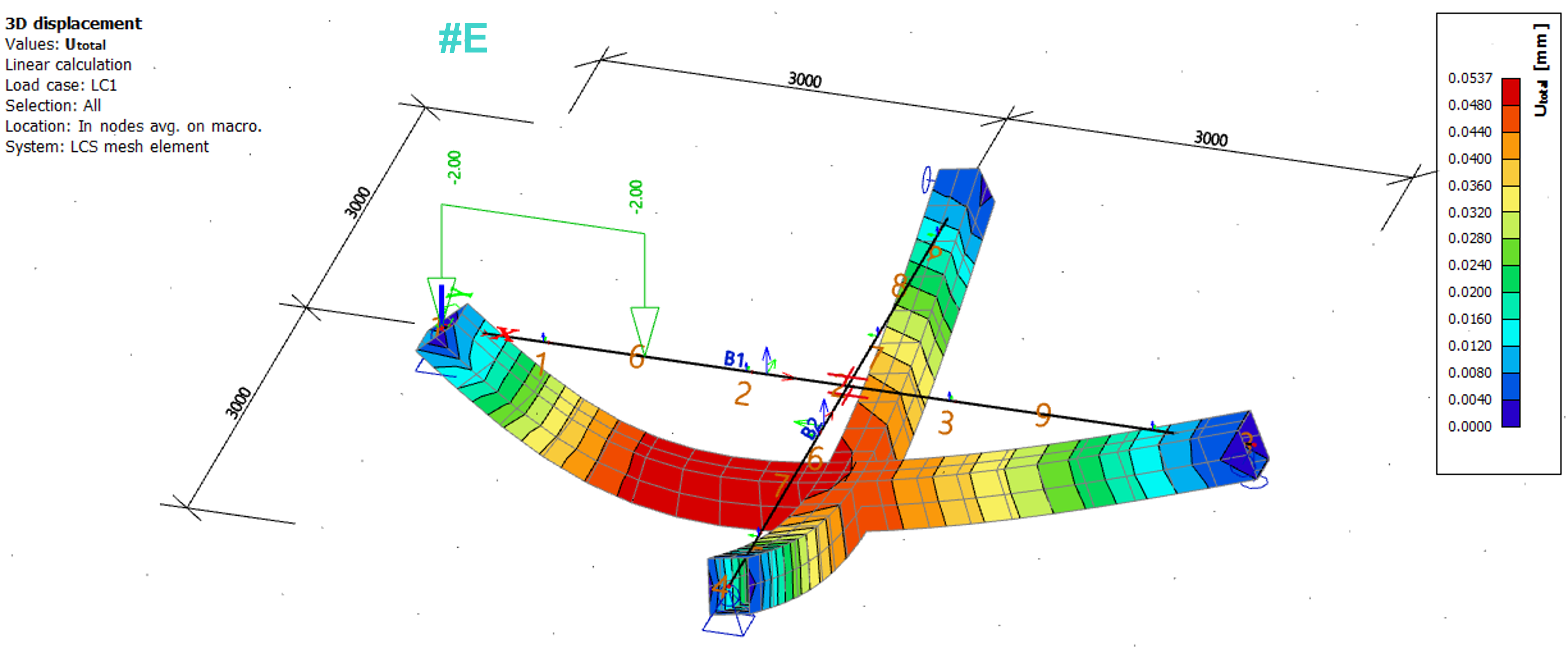
Case #E = In order to connect two crossing beams, crosslink might be defined in this area, in this case the beams will be always coneected.

Case #F1 = one beam ends in the mid-span of the second one. No connection, as the "connect members / nodes" is off.


Case #F2 = one beam ends in the mid-span of the second one. The beams are connected, as the "connect members / nodes" is on.


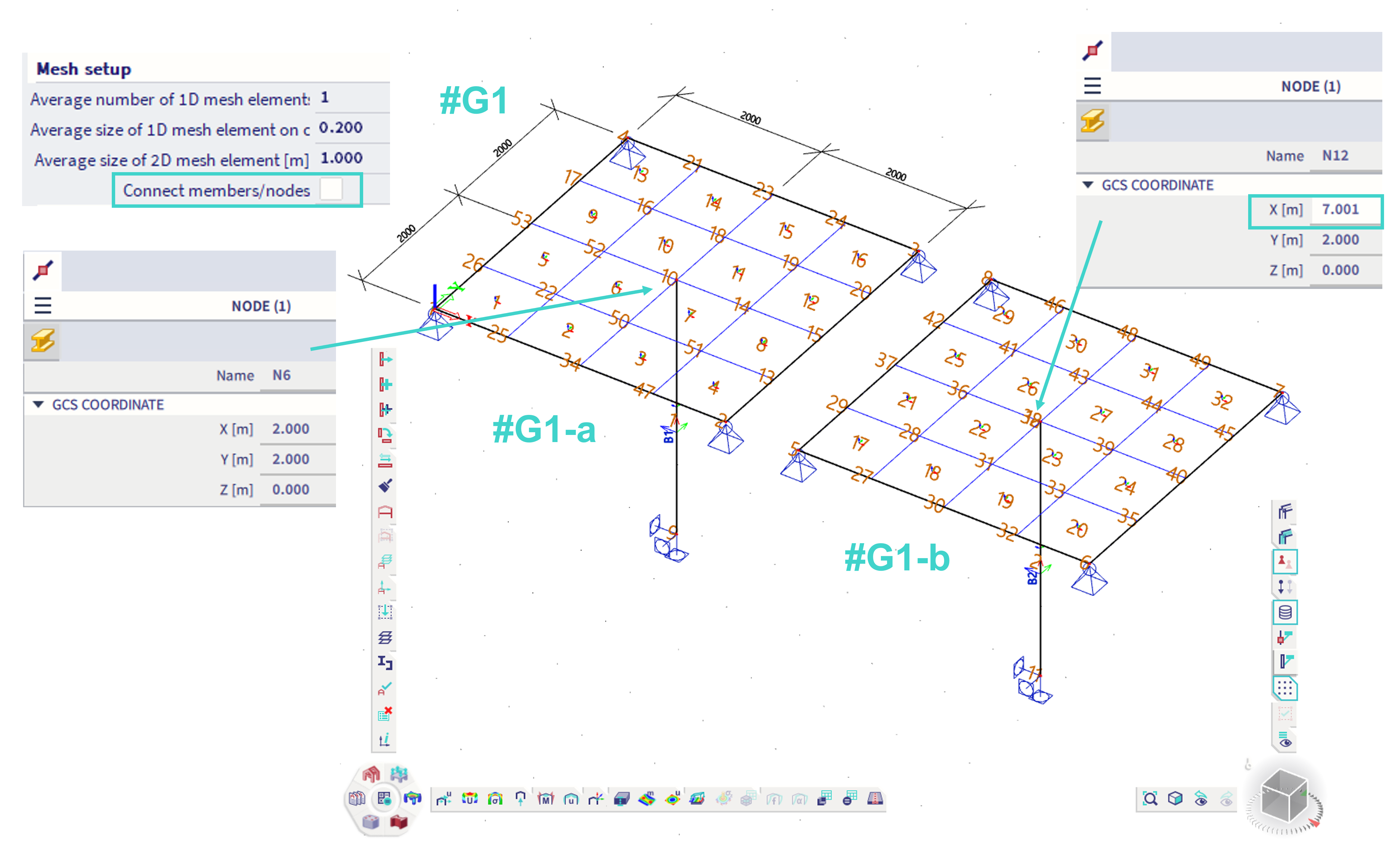
Case #G1 = A head of a column is positioned exactly in a place, where finite element node of 2D structural finite element of slab will be generated (#G1-a). In this case, this column will be connected to the slab also if the "connect members / nodes" is off. In order to avoid this, the upper node of beam needs to be positioned a bit (#G1-b).

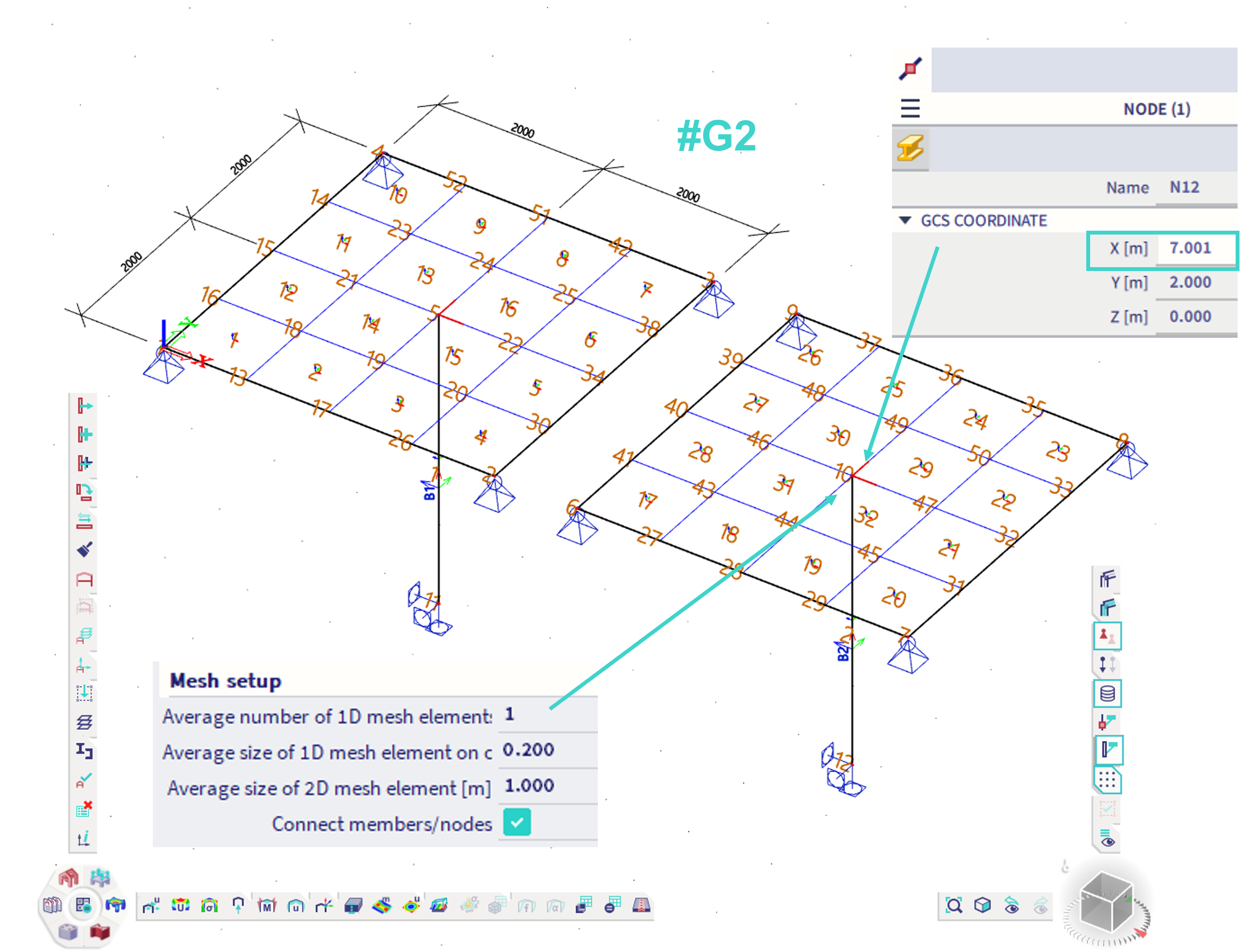
Case #G2 = Column and slab from previous case and the "connect members / nodes" is on. In this case, the both members will be connected.

Case #H = A column which is modelled through the slab. No connection in case of #H-a (there are two coincident finite element nodes due to mesh setting), but again a connection when there is a single force located exactly in the mid-height of the column (#H-b). In order to avoid this, position the force a bit elsewhere (e.g. 0.1 mm upwards), or secure that the mesh node of the slab is not generated exactly in that place.


Conclusion: The users are encouraged always to check the generated finite element mesh. In order to see the labels of finite elements and finite element nodes, it is required to turn on these visibilities in the "view settings for all entities". Also the deformation is always needed to be checked by the user.

Note: This behaviour as described is due to finite element model features