FEM - eccentricity and curved elements
Introduction
This chapter is to provide a closer information about the behaviour of the finite element model.
Features
Eccentricity and curved elements (arcs, cylinders, cones,...)
When there are 1D or 2D elements with defined eccentricities in the model, there is a warning window before the calculation:
An eccentricity of a 1D or 2D curved member (e.g. arc, cylinder,...) has been detected in the model. The eccentricity defined on a member is considered as a pure offset of individual finite elements. However, the 3D window displays the elements as if they are both offset and scaled. As a consequence, any curved structure (arc, cylinder,...) with large eccentricities might show significant differences in results of a self-weight load case. Therefore, it is highly recommended to manually check the eccentricity values of all curved elements (arcs, cylinders, cones,...) and ensure that the eccentricity feature is used suitably and reasonably. Please see the example in our HELP for a detailed explanation.
It is definitely not recommended to utilize large eccentricities in general. However, in case of curved structural elements, like arcs, or cylinders, the user should be aware of this feature.
Example for 1D member - semi-circular arc
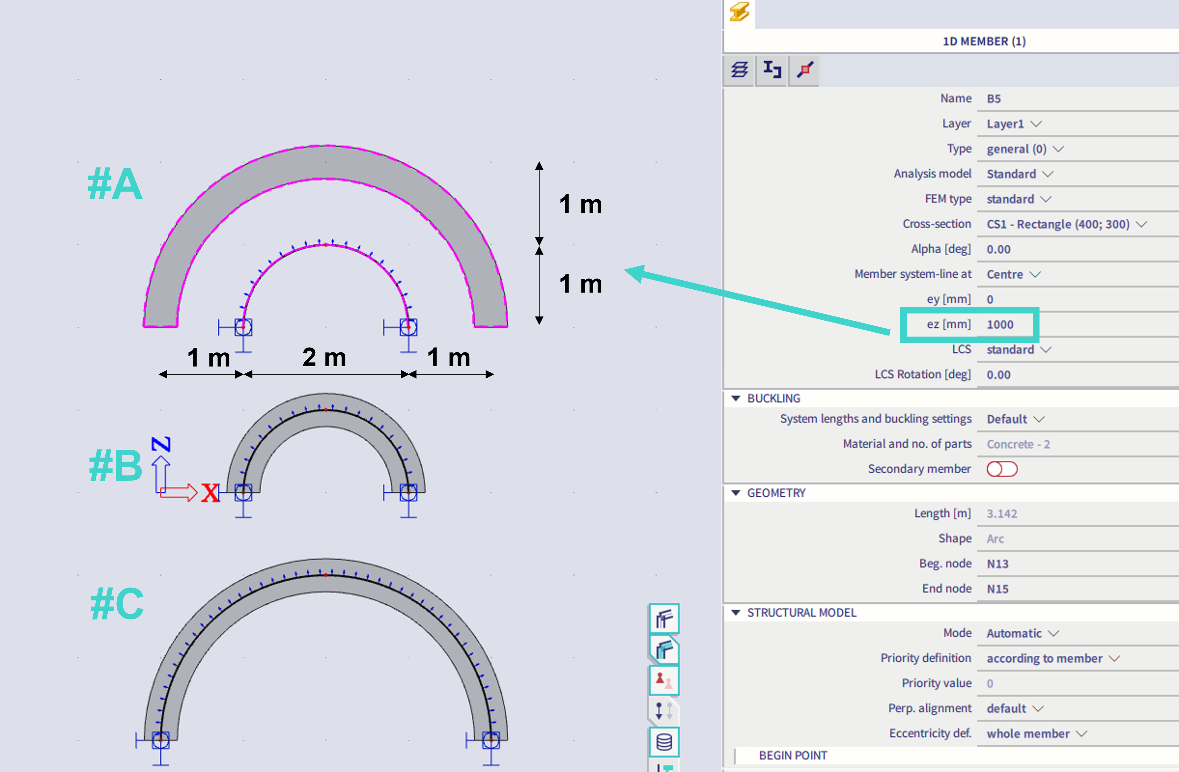
Imagine this incorrectly modelled structure #A compared with properly modelled ones #B, and #C
#A = an arc in a shape of semi-circle of diameter 2m modelled as a 1D beam defined by a semi-circle line of diameter 2m and eccentricity 1m.
#B = correctly modelled semi-circular arc of diameter 2m
#C = correctly modelled semi-circular arc of diameter 4m
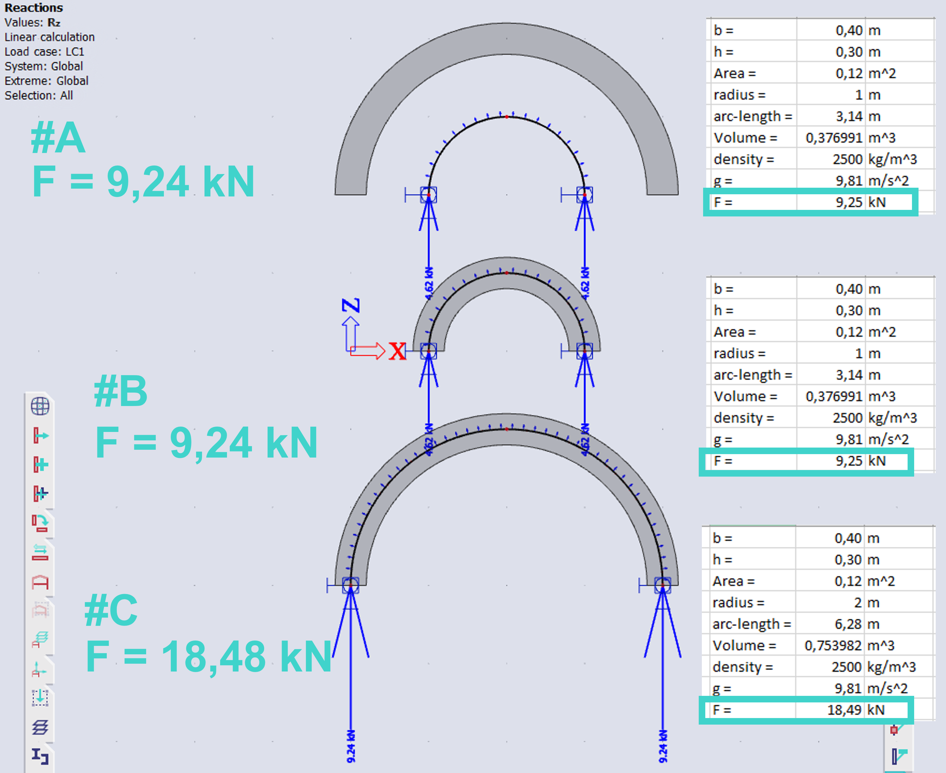
Reaction of the self-weight load case are as below:
The arc #A is in real considered by the same finite element geometry as the arc #B. In case of the arc #A, these are internally considered as only offset by the defined eccentricity (#j), where no scaling is applied (#i). This might be a little confusing, as for the 3D deformations, the finite elements are plotted as if these were scaled (#i), also if the real ratio of the deformation is being plotted.
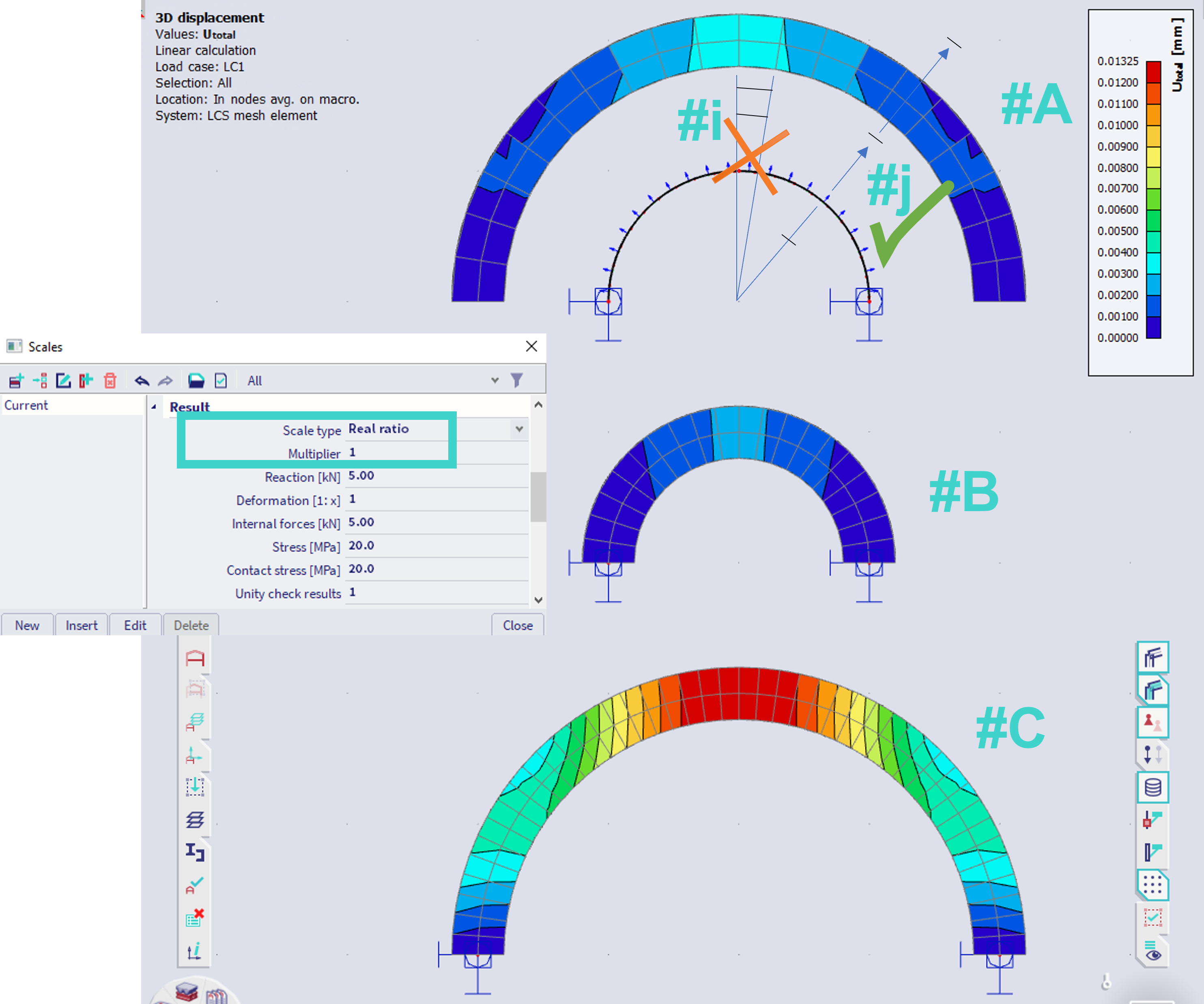
The analogical logic applies for all curved elements and defined eccentricities - e.g. cylinders, cones,... It is recommended not to use large eccentricities.
Note: This behaviour is correct according to the logic of finite elements. The display in the 3D scene is conducted the way it shows continuous mesh, so in case of small eccentricities, the model itself looks smoothly. The logic of display in 3D scene is not distinguished based on defined eccentricity value - hence, the visualization itself is not in match with considered geometry for FE analysis, and leads to incorrect input if large eccentricities are considered.