Hinge on 2D member edge
Definition, application
A connection of two slabs may be modelled as a fixed one or a hinge may be inserted to create a pinned connection. Four configurations of slab hinge are allowed in each direction (translations along X, Y, and Z local 2D member axes, rotation around X local 2D member axes), the condition may be: rigid, free, flexible and nonlinear.
Where to find it
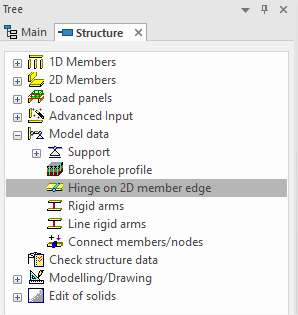
'Hinge on 2D member edge' it is located in Structure / Model data / Hinge on 2D member edge.
How to create new one
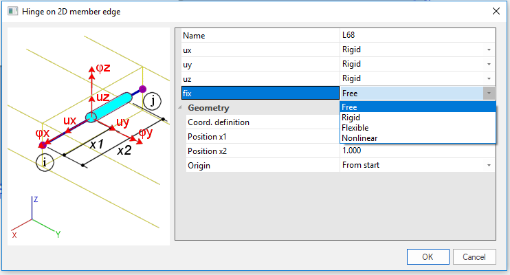
In 'Hinge on 2D member edge' dialog there are possibilities for configuration of behaviour in each degree of freedom (translations along X, Y, and Z local 2D member axes, rotation around X local 2D member axes). After that it is necessary to select edge of 2D member in 3D window where the hinge will be apply. It is not possible to have 2 same hinges on one edge.
Parameters
|
Name |
Specifies the name of the hinge. |
|
ux |
rigid There is no release of degree of freedom defined for the specific direction. The entities are fully connected in this direction like no hinge. free The degree of freedom in the specified direction is released. The two entities are not connected in the given direction. flexibleThere is defined a certain degree of flexibility in the specified direction. The user then has to specify the stiffness of the connection in the given direction. nonlinearThis possibility is available only if functionality 'Local nonlinearities' is ON in Project data dialog. The behaviour of the hinge must be specified by means of a non-linear function. A particular function may be selected in the Hinge property dialogue. Unless the function has been defined earlier, it must be defined when the hinge is being inserted into the model. It is possible to call the Nonlinear function manager directly from the Hinge property dialogue. |
|
uy |
|
|
uz |
|
|
fix |
|
|
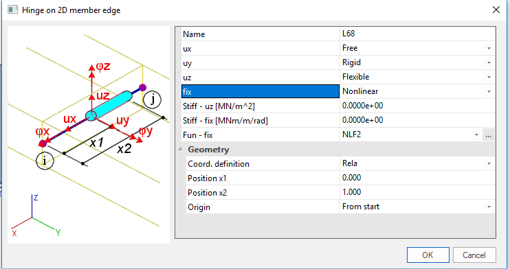
Stiff - ux(uy;uz;fix) |
For a flexible and nonlinear hinge the stiffness must be inputed. For nonlinear analysis for nonlinear hinge this value is only starting value for first iteration. For linear analysis for nonlinear hinge this value is taken into account as flexible hinge with this stiffness. |
|
Fun - ux(uy;uz;fix) |
For a nonlinear hinge a non-linear function must be selected. |
|
Coord. definition |
Selects the coordinate system that is used to define the length of the hinge. |
|
Position x1 |
Defines the starting point of the hinge. By default, the hinge extends along the whole edge of the slab. However, if required, it may be restricted to only a part of the edge. |
|
Position x2 |
Defines the end point of the hinge. |
|
Origin |
Specifies the origin of the coordinate system used for the definition of the length of the hinge. |
Differences between PPE v16 and "default" PPE

- In both PPE basic functionality is the same and in most common cases results will be the same.
- On the background implementation is different, because in "default" PPE hinge is implemented as 1D contact which has possibility to release slabs or has behaviour according some nonlinear function.
- This difference has some small differences in GUI. In 'Hinge on 2D member edge' dialog in PPE v16 there is no possibility to set property on 'nonlinear'. If project is created in "default" PPE and switched to PPE v16 - property 'nonlinear' is automatically switched to 'flexible'.
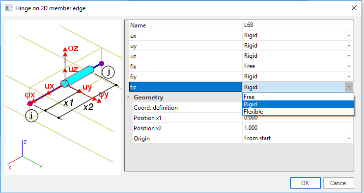
- In PPE v16 there are two more degrees of freedom for hinge: 'fiy' and 'fiz'. This properties are hidden and do not take it into account in "default" PPE. If project is created in "default" PPE and switched to PPE v16 these items will appear as 'rigid'.
Example
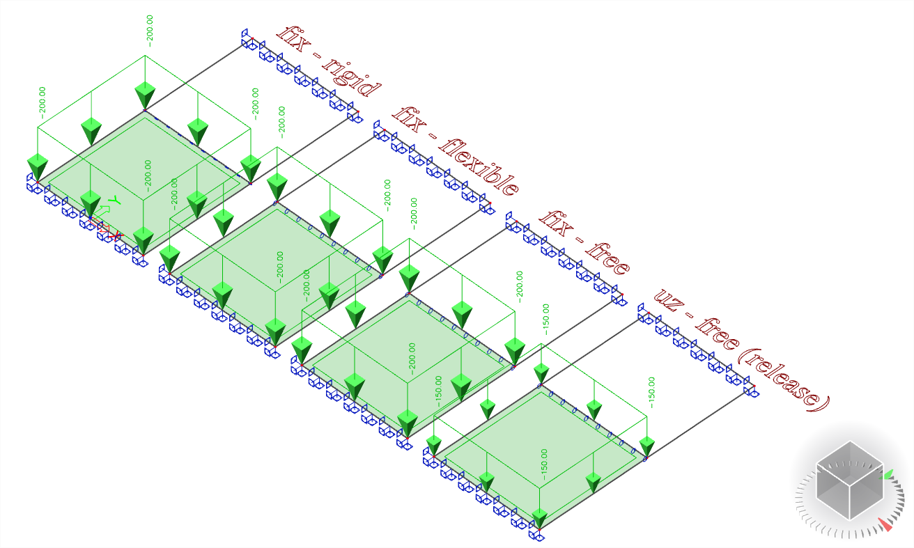
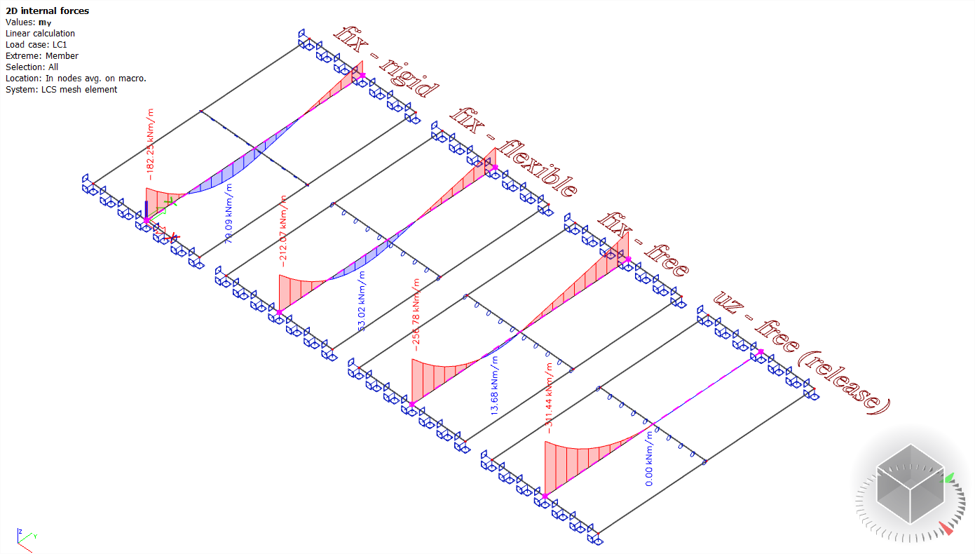
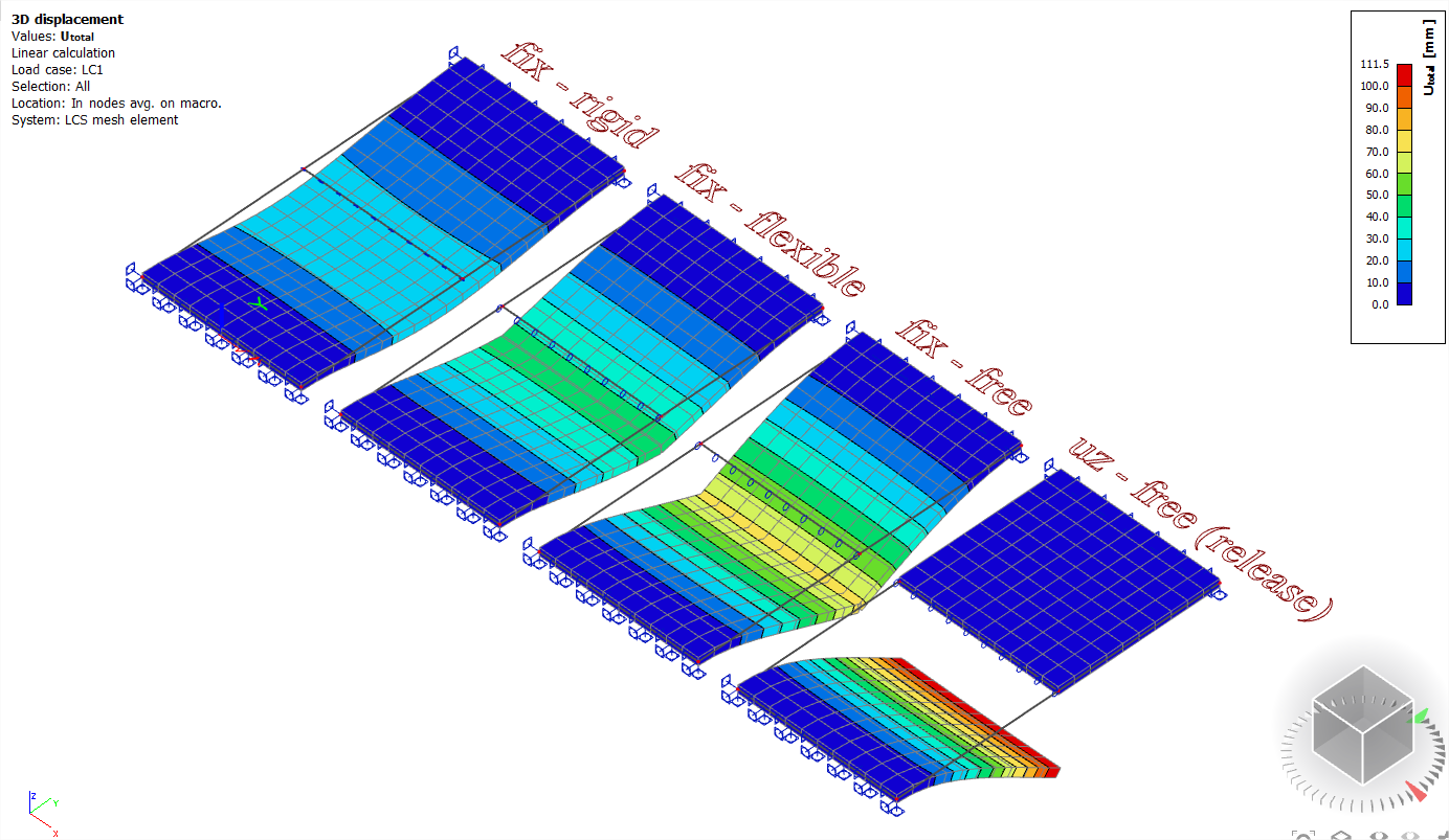
Let’s input four identical rectangular slabs. In fact, each slab consists of two square slabs attached closely to each other. This configuration has been chosen with a view to inserting the hinge. Both ends of both slabs are fixed.
Configurations of hinges are: fix - 'rigid' (no hinge); fix - 'flexible'; fix - 'free'; fix - 'free' + uz - 'free' (release)