Line supports
There are three basic types of linear supports in SCIA Engineer. They are similar to point support types.
|
Standard support |
|
This support is defined by six independent parameters. Each parameter defines the constraint in one direction: translation in X, Y, Z axis and rotation around the same axes. The parameters are the same as for point support except that it is not possible to define non-linear and friction line support. |
|
|
This support is modelled by means of a foundation strip. In addition, some parameters related to the surrounding soil are defined as well. |
|
|
|
This support is used to model the case where the supporting is realised by a wall.
|


Foundation strip
A linear support may be defined in the form of a foundation strip. The supporting is then specified by the properties and dimensions of the strip together with the properties of the soil below and above the footing surface.
This type of support requires the following parameters to be input.
|
Subsoil |
Defines the properties of the soil: C1x, C1y, C2x, C2y, C1z |
|
Width |
Defines the width of the foundation strip: w |
|
Height |
Defines the height of the foundation strip: h |
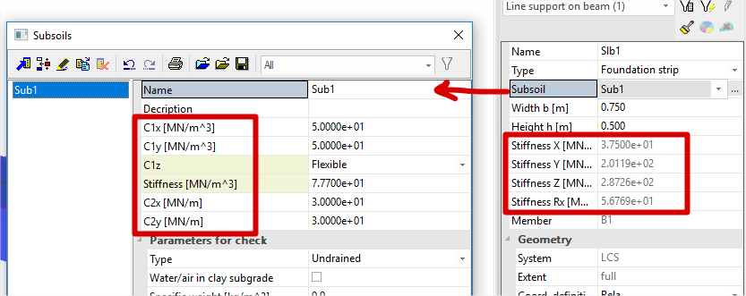
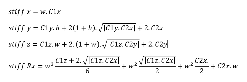
Stiffness parameters are calculated according these formulas :
Note: A foundation block can be used only if the Subsoil functionality has been selected in the Project settings.
Wall
A structure member may be in real life very often supported by a wall. If this is the case and only a part of the real structure is being modelled (e.g. one floor), SCIA Engineer allows definition of such supporting condition with minimal effort.
The program automatically calculates the stiffness of the support from the following parameters:
|
Material |
|
|
Width |
Defines the width of the supporting wall. |
|
Height |
Defines the height of the supporting wall. |
|
Hinged |
Tells whether the wall is rigidly fixed into the supported member or is pinned into it. |
|
Connection |
Determines if the wall is only under the supported member or also above it. |
Note: A supporting wall can be used only if material Concrete has been specified for the project in the Project settings.
Orientation of a linear support on a 1D member
A linear support on a 1D member can be acting:
-
in the direction of global co-ordinate axes,
-
in the direction of axes of the local co-ordinate system of the particular 1D member.
The setting can be made in the property dialogue of each new support.
Formulas for wall support
width w, height h
connection can be single or double (con 1 or 2)
E is E modulus of the material
coeff is 1.0 or 0.75 in case of hinged
the formulas are:
Z = w * E * con / h
Ix = w^3 / 12
Iy = w / 12
Rx = 4 * E * coeff * con * Ix / h
Ry = 4 * E * coeff * con * Iy / h