Environment settings
Parameters affecting the user interface appearance make up this group of Environment settings.
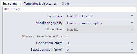
UI settings
|
The item sets the mode that is used for drawing into application graphical windows. |
|
|
Allows smoother rendering. Most visible on inclined lines displayed on rectangular pixel matrix of monitors with low resolution. |
|
|
This option specifies the mode for hidden lines of individual structural entities. |
|
|
Display surfaces intersections |
This check-box allows user to display the intersection of two surfaces. Option is available only for some rendering modes. |
|
This item specifies the style of dashed lines. |
|
|
Select pen width |
Allows user to defined the default width of pen for entities not included in Palette settings (Main menu > View > Colours & lines). |
Rendering
Defines the type of rendering.
| No | This option disables any rendering. The drawing on the screen is fast but reverse surfaces of the structure cannot be hidden. |
| No (calculate hidden lines) | This option disables any rendering but allows reverse surfaces of the structure to be hidden. It is slow way of displaying of the model since the visibility of lines is calculated by the processor. |
| Software OpenGL (emulation) | This options uses the computer's processor to simulate the rendering capability by means of software algorithms. This option should work properly on all computers. It may lead to a longer response of the computer during regeneration of the screen, however it may be useful in case of problems with graphic card. |
| Hardware OpenGL | If this option is selected, the hardware rendering capability of the computer's graphic card is employed. This option may lead to a "distorted" display on some computers, especially those with older models of graphic cards. |
| Hardware OpenGL (full) | This option is similar to 'Hardware OpenGL' with some additional rendering capabilities: volumes can be rendered during commands execution (such as input, copy, move, etc.). With this setting, there are additional options (Wired, Transparent with back edges, Solid with back edges, or Solid) for preselection and selection highlighting and edited entities rendering in the 'Advanced graphics setup'. |
When using 'Open GL (full)' is used, it is recommended to set 'Select pen width [pixel]' to a value of 3 or higher in order to see the highlighting of members when surfaces are not turned on.
From version 18, SCIA Engineer introduced the Navicube 3D navigation system. That system is available only with hardware OpenGL rendering. Compatibility issues have been noted on some computer systems, when 3D accelerations are not properly supported. For more details, see OpenGL textures troubleshooting.
Hidden lines
The Hidden lines option serves as a substitute for full and proper rendering if the Rendering itself is disabled.
The available options are:
|
Invisible |
The hidden lines (hidden parts of entity surfaces) are not drawn at all. |
|
Dashed |
The hidden lines are drawn in dashed style. |
In addition to the above-mentioned options, it is possible to select whether the intersections of individual surfaces should be calculated and displayed.
Note: The settings made here determine which mode of rendering and hidden line display is set for the application. This setting does not mean that the rendering of the scene (i.e. of what is displayed on the screen) is really applied. To do so, the rendering must be switched on for the required graphical window. This can be done by means of the appropriate view parameter for the appropriate graphical window.
Line pattern length
This item affects the style of dashed lines. The dashed lines may be used whenever within the projects. Any dashed line is controlled by this item.
Small number means short lines used in the dashed line with smaller gaps in between.
Large number means long lines used in the dashed line with longer gaps in between.
Command settings
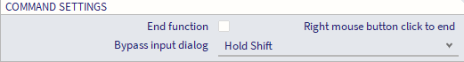
Following setting is related to using commands in SCIA Spotlight.
For setting the application options, see chapter Adjusting the application options.