Longitudinal Shear
The longitudinal shear check is based on the y-y span length and requires only 1 member in a span. If more members are found in a span, the check will end up with an error of 999.
As given by EN 1994-1-1, 6.7.4.2 (2), a column length should be split into three areas:
- Areas of load introduction with length lvi not exceeding 2d or Ly/3, where d is the minimum transverse dimension (bc ,hc (d in case of CHS)) of the column cross-section and L is the y-y span length. These areas are located at the start and end of the column.
- Area outside of load introduction which lies between the two areas from above (lvo=L-2*lvi). As given by EN 1994-1-1, 6.7.4.1 (3), for axially loaded columns and compression members (= pure compression), longitudinal shear outside the areas of load introduction need not be considered. In this case a note will be displayed and unity check is set to 0 for related sections.
For both inside and outside areas, longitudinal shear at the interface between concrete and steel is verified. Shear connectors should be provided, based on the distribution of the design value of longitudinal shear τEd, where this exceeds the design shear strength τRd. Provided that the surface of the steel section in contact with the concrete is unpainted and free from oil, grease and loose scale or rust, the values given in EN 1994-1-1, Table 6.6 may be assumed for τRd.
Design longitudinal shear stress of checked area
Design longitudinal shear stress is calculated using formula initially based on Composite Structures of Steel and Concrete, R.P. Johnson, 2004 equation 5.34, but in SCIA Engineer extended with bending moment effect. Only effect of bending moment around y-axis is considered in the whole longitudinal calculation!

with:
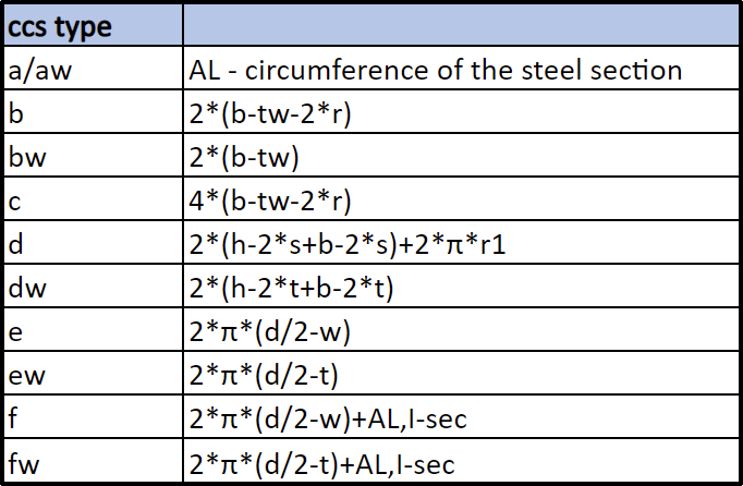
ua - length of the effective steel-concrete perimeter
lv – length of the checked area (lvi or lvo)
z – lever arm for strong-axis bending ( depending on css type h, hc or d)
zcoeff - lever arm coefficient defined in the composite setup
Design forces in structural steel
Na,Ed – design normal force in structural steel

NEd – design normal force in checked area (maximum value in checked area)
Npl,a - compression resistance of structural steel
Npl,Rd - compression resistance of composite section
Mpl,a,y - bending moment resistance of structural steel

My,Ed – design bending moment around y axis in checked area (maximum value in checked area)
Ma,y,Ed – design bending moment in structural steel
Mpl,y,Rd - bending moment resistance of composite section
Design forces in reinforced concrete


Longitudinal shear is verified using formula below:

with:
ΤEd – design longitudinal shear stress
ΤRd – longitudinal shear stress resistance given by EN 1994-1-1, Table 6.6. If conditions given by EN 1994-1-1, 6.7.4.3 (4) for completely concrete encased steel sections (types a/aw) are fulfilled, initial resistance ΤRd may be increased by coefficient βc (6.49) and verification formula is then modified to:

with:

cz - concrete cover
cz,min - minimum concrete cover required (40 mm)
cf - internal SCIA Engineer coefficient introduced to fix units of cz (expected to be used in mm in the formula).
assuming that:
• a minimum concrete cover of 40 mm is applied
• transverse and longitudinal reinforcement in accordance with 6.7.5.2. (minimum (0,3 %) and maximum (6%) longitudinal percentage checked)
If the shear strength is not sufficient, the shear connectors must be added. Depending on cross-section type either warning (c, d/dw, e/ew, f/fw) or note (css a/aw, b/bw) is displayed.
Headed studs check
The check of headed studs is only supported for fully or partially-encased cross-sections of type a/aw and b/bw.
Resistance of the headed stud is given by EN 1994-1-1, 6.6.3.1 as smaller value of resistance PRd,1 (equation 6.18) and resistance PRd,2 (equation 6.19).
As given by EN 1994-1-1, 6.7.4.2 (4) the resistance of each horizontal row of studs may be increased by frictional forces present on the flanges, while fulfilling given geometry limits. Shear resistance of horizontal row is then calculated as:

with:
nrow - number of studs in horizontal row
μ - friction coefficient
Final resistance of headed stud is calculated as:

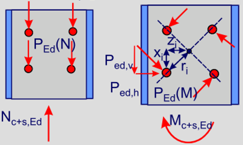
Calculation of the maximum design shear forces on studs is based on "Composite Structures according to Eurocode 4 - Worked Examples" published by Dujmović/Androić/ Lukačević in Zagreb, 2014.
Maximum value according to elastic theory:

with:
n - number of studs within the introduction length
Maximum value according to plastic theory:
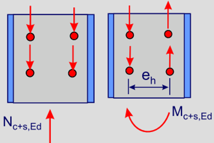

with:
eh - distance between the outer studs
If there is a bending moment My,Ed present, having a single column of studs would lead to division by zero. This will set unity check to 999 and an error will be displayed on the output.
The final verification of the headed studs is verified using formula below:
