User Guide
Project Prerequisites
The floor vibration check in SCIA Engineer is available when 1) the ‘code’ setting in the project is set to ‘IBC’ 2) the ‘structure’ setting in the project is set to ‘General XYZ’ and 3) concrete and steel materials are active. To run the check, results must exist in the project (i.e. the calculation must be run).
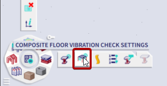
Floor Vibration Setup and Floor Vibration Beam Data
Settings related to how the floor vibration check is implemented in the project can be input in two ways: as floor vibration setup data or as floor vibration beam data. Floor vibration setup inputs are applied to the entire project while floor vibration beam data inputs are applied only to the members to which beam (or member) data is applied. For inputs which are available in both the floor vibration setup and in the floor vibration beam data, the input in the beam data will override the input in the setup.
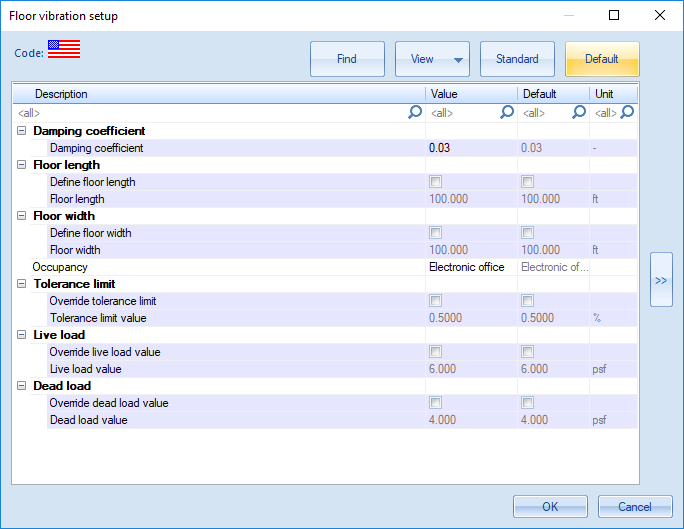
Floor Vibration Setup Options:
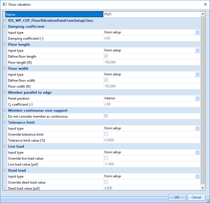
Floor Vibration Beam Data Options:
Floor vibration beam data includes all fields which are found in the setup with the exception of Occupancy Type* and with the addition of the following:
| Panel position |
Option to define a member as parallel to and at a free edge. If member is parallel to a free edge and part of an exterior bay, this setting should be set to ‘Exterior’. When set to ‘Exterior’ the member will receive a ‘Cj coefficient’ value of 1.0, otherwise it will receive a ‘Cj coefficient’ value of 2.0. |
| Do not consider member as continuous | Option to not consider member as continuous and therefore not increase the effective panel weight by 50%. By default, members are considered continuous and the effective panel weight is increased by 50%. |
*Note : Although Occupancy Type cannot be set in member data, if a project consists of a multi-occupancy structure, the live load values and tolerance limits can be manually set as needed in the member data.
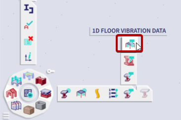
Running Check
Once any desired settings have been made in the setup and/or member data, the results of the check can be displayed by selecting Floor Vibration Check and then selecting Refresh in the properties window. A result value and selection can be set as needed. Note that the selection option only determines for which members the results are shown. By the nature of this check, all members in the project must be processed in the calculation. Additionally, it should be noted that no load case or combination is needed for the floor vibration check. Dead and live loads are simply defined in the setup or member data. The live load is based on the occupancy type by default and a dead load value of 4 psf is used by default.
Output and Results
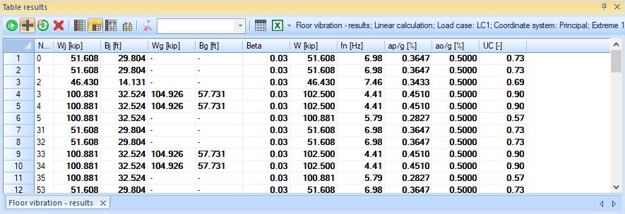
Final results (such as the Acceleration relative to gravity and Unity check) as well as the intermediate result values can then be viewed in the Engineering Report Preview by clicking Preview or viewed in a table layout by clicking Table Results.