Composite Model Considerations
Setting Up Cross-Sections Groups in Model
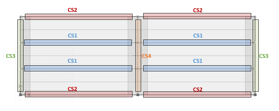
When building a model in SCIA that contains composite members, some consideration should be made to create cross-section groups that contain members with similar tributary areas. Because auto-design is performed on cross-section groups and all members in the group are designed based on the worst-case member in the group, grouping in this way will prevent some members from being considerably over-designed or under-designed.
The following diagram shows an example of how cross-sections should be grouped:
1D Member Properties
In SCIA, composite members are modelled as 1D plate rib members. Ribs can be added to a 2D member in two ways:
1) by direct input using the rib input functionality (Structure service under 1D members or under 2D members/2D member components)

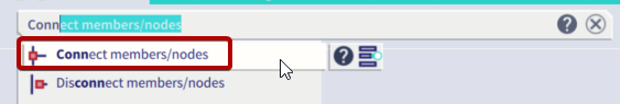
or 2) by adding beams or members and using the “Connect members/nodes” tool.
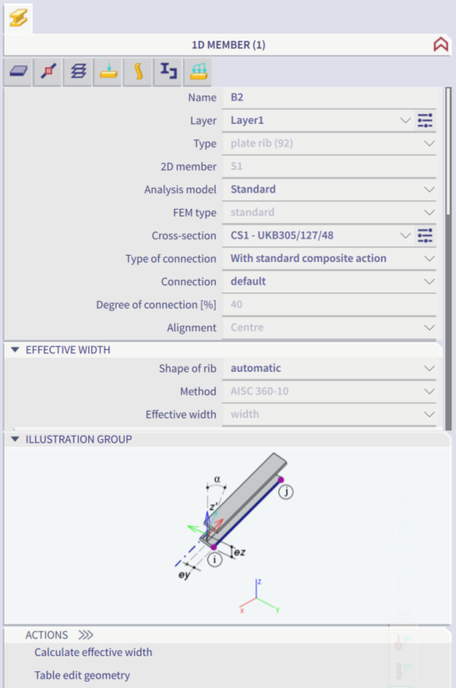
The following 1D member properties must be used when designing composite members:
• Type of Connection should be set to “With standard composite action” (default setting) to indicate that a connection exists between the steel member and the concrete slab. Alternatively, if there is no connection and the deck is supported by the beam, set Type of Connection to “Without composite action”. The option for “With advanced composite action” models the plate rib with its real eccentricity, but is not compatible with the composite beam design module.
• Shape of rib should be set to “automatic” in order for the effective width of the member to be automatically calculated. The effective width can be calculated by clicking “Calculate effective width” under Actions. Alternatively, the effective width can be defined manually by setting Shape of rib to T-symmetric, slab left, slab right, or asymmetric.
2D Member Properties
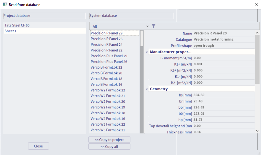
It is a requirement for the 2D Member properties that the Element type be set to “Composite deck”. When this is the case, the decking library becomes available. SCIA Engineer contains a full library of metal deck profiles. To access this library, click the blue folder icon (“read from system database”) from within the profile sheeting dialog when adding a new 2D member or when updating the current profile. Select the desired profile and click “Copy to project” to make it available in the model.
Additionally, it is recommended that the Element behaviour be set to "Rigid diaphragm."
For a more detailed description of all Element behaviours, see 2D Member Element Types & Behaviours.
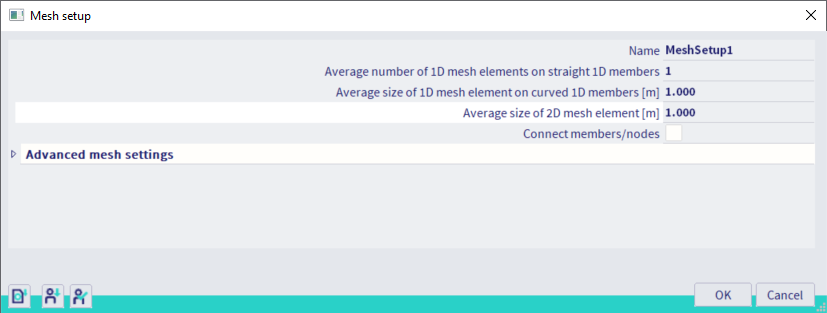
Mesh Size
As with any finite element model, some consideration should be given to the size of the mesh before running an analysis. A trade-off between precision and speed exists as the size of the mesh is adjusted. If the element behaviour is set to "Standard FEM" (and not "Rigid diaphragm" as recommended), it is generally recommended that the Average size of 2d element/curved element be set to a value approximately one-tenth of the average member length or one-tenth of the shortest member if needed. For most projects, a mesh size of 3ft is reasonable.