Solver settings
Design As
Coefficient for reduction of strength of the concrete in compressive concrete
Beam, Column, Rib, Beam Slab
Limit ratio of bending moment for uni axial method
|
Description |
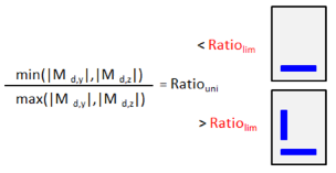
Limit ratio of bending moments for using uniaxial design method. If ratio of bending moments is lesser than limit ratio, uniaxial design method is used and smaller value of bending moment and shear force is neglected. |
|
Default |
Edit box; default ρM,lim = 0,1 |
|
Code |
- |
|
Level |
Advanced |
|
Figure |
|
|
Member |
Design method (beams)
|
Description |
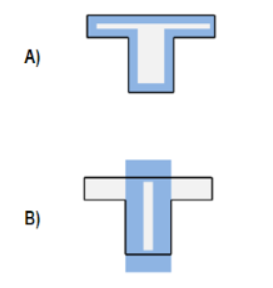
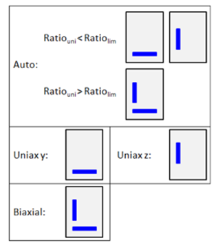
Method for design of longitudinal reinforcement for beams. Auto - Automatic determination of design method according to bending moments ratio ρM. Uniaxial around z - Design for uniaxial bending moment Mz only. Moment My will not be taken into account (My = 0 kNm). Uniaxial around y - Design for uniaxial bending moment My only. Moment Mz will not be taken into account (Mz = 0 kNm). Biaxial - Design for biaxial bending for both bending moments My and Mz. |
|
Default |
Combo box; default = Auto |
|
Code |
- |
|
Level |
Advanced |
|
Figure |
|
|
Member |
Beam, Beam slab, Rib |

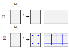
Design method (columns)
|
Description |
Method for design of longitudinal reinforcement for columns. Auto - Automatic determination of design method according to bending moments ratio ρM. Uniaxial around z - Design for uniaxial bending moment Mz only. Moment My will not be taken into account (My = 0 kNm). Uniaxial around y - Design for uniaxial bending moment My only. Moment Mz will not be taken into account (Mz = 0 kNm). Biaxial - Design for biaxial bending for both bending moments My and Mz. |
|
Default |
Combo box; default = Auto |
|
Code |
- |
|
Level |
Advanced |
|
Figure |
|
|
Member |
Column |
Coefficient increasing statically required reinforcement in beam for upper surface
|
Description |
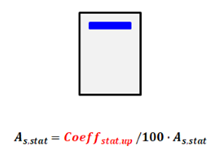
Increasing statically required reinforcement at upper surfaces for beam, beam slab and rib. . |
|
Default |
Edit box; Coeffstat.up = 100% |
|
Code |
- |
|
Level |
Advanced |
|
Figure |
|
|
Member |
Beam, Beam slab, Rib |
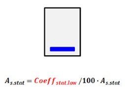
Coefficient increasing statically required reinforcement in beam for lower surface
|
Description |
Increasing statically required reinforcement at lower surfaces for beam, beam slab and rib. . |
|
Default |
Edit box; Coeffstat.low = 100% |
|
Code |
- |
|
Level |
Advanced |
|
Figure |
|
|
Member |
Beam, Beam slab, Rib |
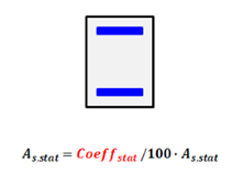
Coefficient increasing statically required reinforcement for column
|
Description |
Increasing statically required reinforcement at lower surfaces for columns . |
|
Default |
Edit box; Coeffstat= 100% |
|
Code |
- |
|
Level |
Advanced |
|
Figure |
|
|
Member |
Column |
Design longitudinal and shear reinforcement due to torsion
|
Description |
Longitudinal and shear reinforcement due to torsion is not designed if the check box is set False . |
|
Default |
Check box; default = True |
|
Code |
- |
|
Level |
Advanced |
|
Figure |
|
|
Member |
1D (Beam, Beam slab, Column, Rib) |
Plate, Wall, Shell(Plate), Shell(Wall), Deep Beam
Modification of the statically required area of reinforcement for the upper surface of Plate, Shell(Plate)
|
Description |
Increasing statically required reinforcement for upper surface of Plate, Shell(Plate). As,stat = Coeffstat.up.2D/100 ∙ As,stat |
|
Default |
Edit box; Coeffstat.up.2D = 0,0 |
|
Code |
- |
|
Level |
Advanced |
|
Figure |
- |
|
Member |
Plate, Shell(Plate) |
Modification of the statically required area of reinforcement for the lower surface of Plate, Shell(Plate)
|
Description |
Increasing statically required reinforcement for lower surface of Plate, Shell(Plate). As,stat = Coeffstat.lo.2D/100 ∙ As,stat |
|
Default |
Edit box; Coeffstat.lo.2D = 0,0 |
|
Code |
- |
|
Level |
Advanced |
|
Figure |
- |
|
Member |
Plate, Shell(Plate) |
Modification of the statically required area of reinforcement for both layers in Wall, Shell(Wall) and Deep Beam
|
Description |
Increasing the statically required reinforcement for both surfaces of Wall and Shell(Wall). As,stat = Coeffstat.both.2D/100 ∙ As,stat |
|
Default |
Edit box; Coeffstat.both.2D = 0,0 |
|
Code |
- |
|
Level |
Advanced |
|
Figure |
- |
|
Member |
Wall, Shell(Wall), Deep beam |
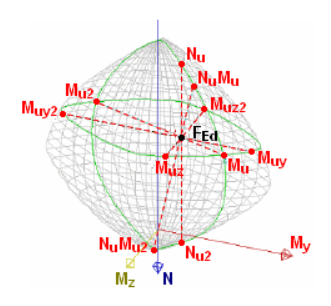
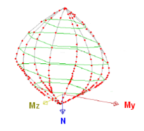
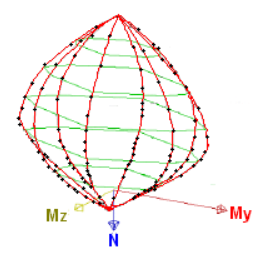
Interaction diagram
Interaction diagram method
|
Description |
Possibility to set method for evaluation of results using interaction diagram: - NRd - assuming Md is constant - MRd - assuming Nd is constant - NRdMrd - assuming eccentricity is constant - - assuming Mdz is constant - - assuming Mdy is constant |
|
Default |
Combo box; default = NRdMRd |
|
Code |
- |
|
Level |
Standard |
|
Figure |
|
|
Member |
All |
Division of strain
|
Description |
Calculation precision for one of the diagram “branches” during generation of interaction diagram. The value means how many times the strain plane is readjusted from the position of section under full compression to the position of section under full tension. |
|
Default |
Edit box; default = 250 |
|
Code |
- |
|
Level |
Advanced |
|
Figure |
|
|
Member |
1D (Beam, Beam slab, Column, Rib) |
Number of points in vertical cut
|
Description |
Number of directions in which the interaction diagram is calculated (number of “branches”) during generation of interaction diagram. |
|
Default |
Edit box; default = 36 |
|
Code |
- |
|
Level |
Advanced |
|
Figure |
|
|
Member |
1D (Beam, Beam slab, Column, Rib) |
Shear
Type calculation / input of angle of compression strut
|
Description |
Type calculation of angle of between of compression strut and member axis for shear check. - Auto - automatic calculation of minimum angle based on condition Vd ≤ VRd.max - User(angle) - the value is inputted by the user as angle - User(cotangent) - the value is inputted by the user as cotangent of the value |
|
Default |
Combo box; default = User(angle) |
|
Code |
4.3.3.3.2 |
|
Level |
Standard |
|
Figure |
|
|
Member |
All |
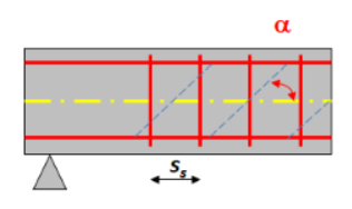
Angle of compression strut
|
Description |
Angle between of compression strut and member axis for shear check; editable only if type of calculation of compression strut angle is User (angle) |
|
Default |
Edit box; θ = 40 ° |
|
Code |
4.3.3.3.2 |
|
Level |
Standard |
|
Figure |
|
|
Member |
All |
Cotangent angel of compression strut
|
Description |
Cotangent angle between of compression strut and member axis for shear check; editable only if type of calculation of compression strut angle is User (cotangent) |
|
Default |
Edit box; cot(θ) =1,2 |
|
Code |
4.3.3.3.2 |
|
Level |
Standard |
|
Figure |
|
|
Member |
All |
Torsion
Equivalent thin walled cross-section
|
Description |
Type of equivalent thin-walled cross-section used for calculation of cross-section capacity in torsion. From used CSS - The program tries to create equivalent thin-walled cross-section from current cross-section by offsetting the value tef. |
|
Default |
Combo box; default = Automatic |
|
Code |
4.3.5 |
|
Level |
Advanced |
|
Figure |
|
|
Member |
1D (Beam, Beam slab, Column, Rib) |
|
|
|