Concrete member data
Concrete member data automation
There is a new feature from version SCIA Engineer 22 which automatically creates concrete member data for each 1D and 2D element in the structure.The concrete member data will be automatically created for member (1D or 2D) immediately after created 1D or 2D member. Default properties in concrete member data will be loaded form global setting (concrete setting). This behaviour simplify the user work-flow and speed up the whole process. The advantage is when the default value is changed in Global setup then its automatically propagated into all Concrete member data where this value is unchanged towards to Global setup. As the all member have concrete member data generated, the visibility is automatically switch ON just for of member where different values than in global setup are presented.
This procedure works for new and old SCIA Engineer projects. When you open old SCIA Engineer file in version SCIA Engineer 22 then concrete member data are automatically generated for the member where concrete member data were not defined on.
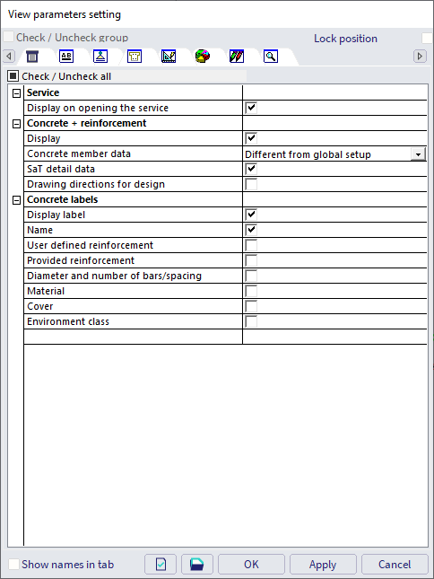
Of course there are also other options how to make a concrete member data visible in 3D window:
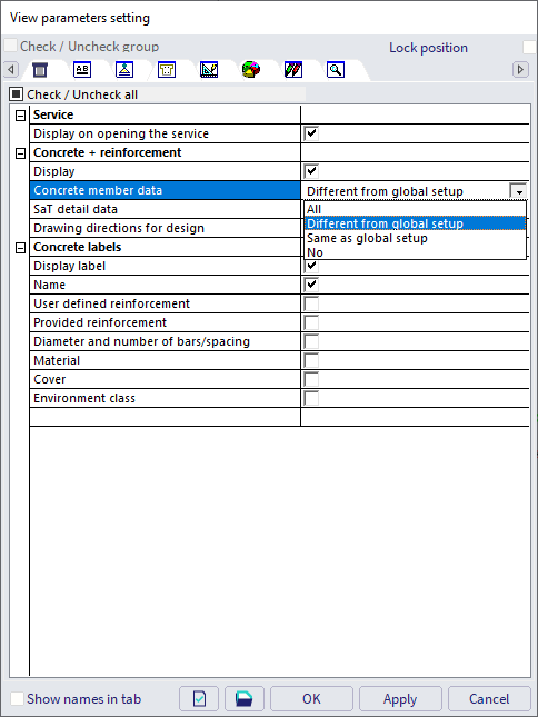
- All - all member data are visible independently
- Different from global setup - just concrete member data which are changed towards to Global setup are visible only
- Same as global setup - just concrete member data which are unchanged towards to Global setup are visible only
- No - none of concrete member data are visible
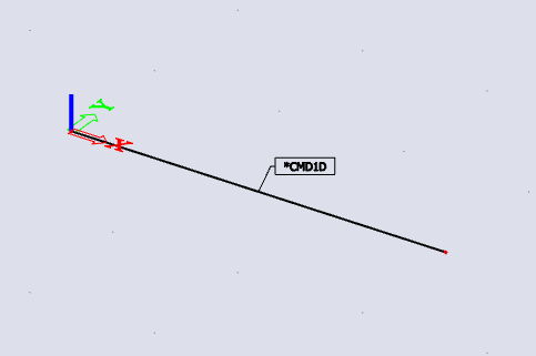
When the Concrete member data are changed towards to Global setup then its also indicated in the 3D window by asterisk (*).
When you select concrete member data you can also clearly see which item is different from Global setup by orange colour.
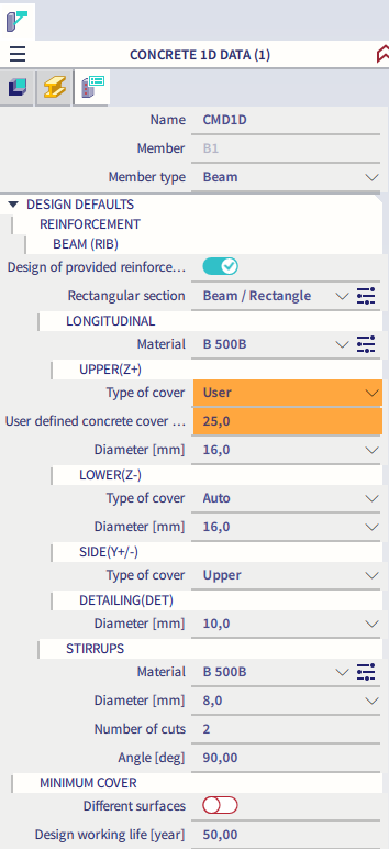
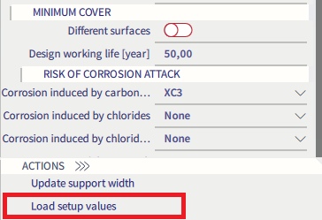
Clicking on the Load setup value button in Concrete member data the values are automatically synchronized to values presented in Global setup.
Concrete member data and Global setup in Engineering Report.
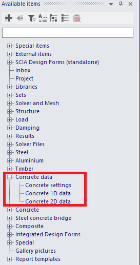
There is also possibility to input Global setup and concrete member data into Engineering Report. see the list of available items in Concrete data.
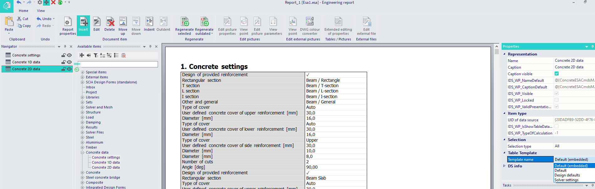
When you insert Concrete settings it looks as follows with three different Template names
- Default
- Design defaults
- Solver settings
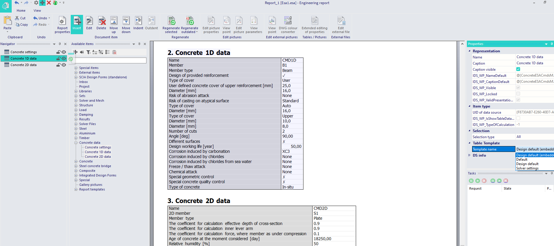
Similarly it works for Concrete 1D and 2D member data
1D member data/Integration member
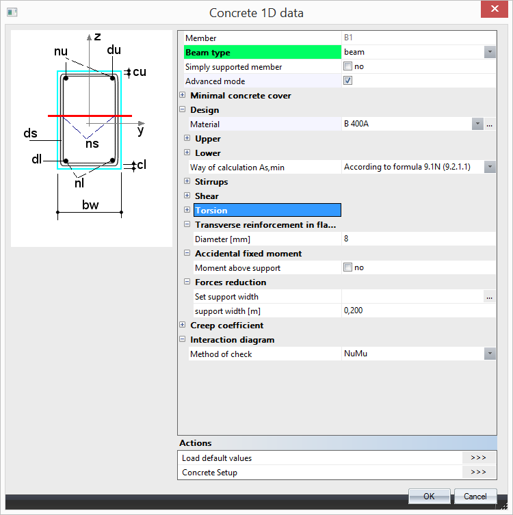
These settings overwrite the global settings for a specific member. Member data can easily be copy-pasted to similar members. There is differentiation based on type of member (beam, column, beam slab, rib). As in the case of setup, Member data has been also restyled. Local settings contains a contain about the same input parameters and calculation settings as the global settings in setup. Moreover, user can set his/her own value of limit deflection and limit width of crack, define more environmental classes than just one as in previous version.
|
|
| Concrete Advanced member data | Concrete member data |
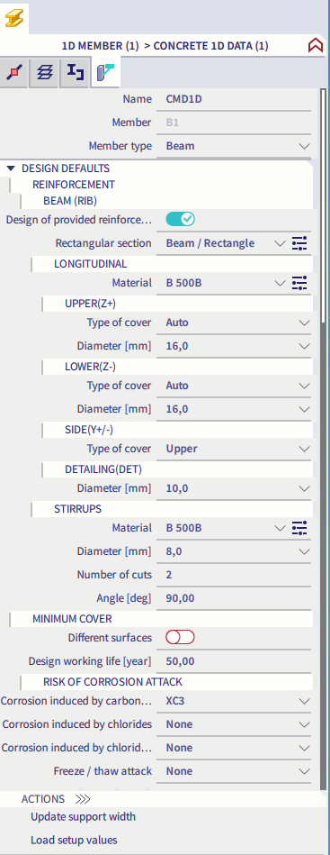
Properties of 1D Member data
1D Member data are arranged similarly as Concrete settings (structure). Generally, there are the following items.
- Name – name of the member data
- Member – name of the associated member
- Member type – generally member data can be set for Beam, Columns, Beam Slab and Rib differently.
- Design defaults
- Solver settings
Design defaults
Reinforcement
Beam/Rib
Longitudinal
Use a template of provided reinforcement
| Description |
Information about if the template of provided reinforcement is used or not |
| Default | Checkbox - ON |
|
Code |
- |
| Level | Standard |
|
Figure |
- |
| Member | Beam / Rib |
Upper
Diameter of upper reinforcement
| Description |
Information about diameter of upper of reinforcement |
| Default | Edit box; default ds,u = 16 mm |
|
Code |
- |
| Level | Standard |
|
Figure |
|
| Member | Beam / Rib |
Type of cover of upper reinforcement
| Description |
Information about type of cover of upper reinforcement |
| Default | Combo box; Auto / User; default = Auto |
|
Code |
4.4.1 |
| Level | Standard |
|
Figure |
|
| Member | Beam / Rib |
User defined concrete cover of upper reinforcement
| Description |
Possibility to define concrete cover of upper reinforcement; this item is visible only if the item above is set to User |
| Default | Edit box; cu = 30 mm |
|
Code |
4.4.1 |
| Level | Standard |
|
Figure |
|
| Member | Beam / Rib |
Lower
Diameter of lower reinforcement
| Description |
Information about diameter of lower of reinforcement |
| Default | Edit box; default ds,l = 16 mm |
|
Code |
- |
| Level | Standard |
|
Figure |
|
| Member | Beam / Rib |
Type of cover of lower reinforcement
| Description |
Information about type of cover of lower reinforcement |
| Default | Combo box; Auto / User; default = Auto |
|
Code |
4.4.1 |
| Level | Standard |
|
Figure |
|
| Member | Beam / Rib |
User defined concrete cover of lower reinforcement
| Description |
Possibility to define concrete cover of lower reinforcement; this item is visible only if the item above is set to User |
| Default | Edit box; cl = 30 mm |
|
Code |
4.4.1 |
| Level | Standard |
|
Figure |
|
| Member | Beam / Rib |
Side
Type of cover of side reinforcement
| Description |
Information about type of cover of side reinforcement |
| Default | Combo box; Auto / User; default = Auto |
|
Code |
4.4.1 |
| Level | Standard |
|
Figure |
|
| Member | Beam / Rib |
User defined concrete cover of side reinforcement
| Description |
Possibility to define concrete cover of side reinforcement; this item is visible only if the item above is set to User |
| Default | Edit box; cs = 30 mm |
|
Code |
4.4.1 |
| Level | Standard |
|
Figure |
|
| Member | Beam / Rib |
Stirrups
Diameter of stirrups
| Description |
Information about diameter of stirrups |
| Default | Edit box; dss = 8 mm |
|
Code |
- |
| Level | Standard |
|
Figure |
|
| Member | Beam / Rib |
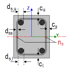
Number of cuts
| Description |
Information about number of cuts for shear reinforcement |
| Default | Edit box; ns = 2 |
|
Code |
- |
| Level | Standard |
|
Figure |
|
| Member | Beam / Rib |
Angle
| Description |
Angle between shear reinforcement and the beam axis perpendicular to the shear force |
| Default | Edit box; α = 90 ° |
|
Code |
- |
| Level | Standard |
|
Figure |
- |
| Member | Beam / Rib |
Beam slab
Longitudinal
Upper
Diameter of upper reinforcement
| Description |
Information about diameter of upper of reinforcement |
| Default | Edit box; default ds,u = 16 mm |
|
Code |
- |
| Level | Standard |
|
Figure |
|
| Member | Beam slab |
Type of cover of upper reinforcement
| Description |
Information about type of cover of upper reinforcement |
| Default | Combo box; Auto / User; default = Auto |
|
Code |
4.4.1 |
| Level | Standard |
|
Figure |
|
| Member | Beam slab |
User defined concrete cover of upper reinforcement
| Description |
Possibility to define concrete cover of upper reinforcement; this item is visible only if the item above is set to User |
| Default | Edit box; cu = 30 mm |
|
Code |
4.4.1 |
| Level | Standard |
|
Figure |
|
| Member | Beam slab |
Lower
Diameter of lower reinforcement
| Description |
Information about diameter of lower of reinforcement |
| Default | Edit box; default ds,l = 16 mm |
|
Code |
- |
| Level | Standard |
|
Figure |
|
| Member | Beam slab |
Type of cover of lower reinforcement
| Description |
Information about type of cover of lower reinforcement |
| Default | Combo box; Auto / User; default = Auto |
|
Code |
4.4.1 |
| Level | Standard |
|
Figure |
|
| Member | Beam slab |
User defined concrete cover of lower reinforcement
| Description |
Possibility to define concrete cover of lower reinforcement; this item is visible only if the item above is set to User |
| Default | Edit box; cl = 30 mm |
|
Code |
4.4.1 |
| Level | Standard |
|
Figure |
|
| Member | Beam slab |
Column
Longitudinal
Main
Diameter of main reinforcement
| Description |
Information about diameter of main of reinforcement |
| Default | Edit box; default ds,m = 16 mm |
|
Code |
- |
| Level | Standard |
|
Figure |
|
| Member | Column |
Type of cover of main reinforcement
| Description |
Information about type of cover of main reinforcement |
| Default | Combo box; Auto / User; default = Auto |
|
Code |
4.4.1 |
| Level | Standard |
|
Figure |
|
| Member | Column |
User defined concrete cover of main reinforcement
| Description |
Possibility to define concrete cover of main reinforcement; this item is visible only if the item above is set to User |
| Default | Edit box; cm = 30 mm |
|
Code |
4.4.1 |
| Level | Standard |
|
Figure |
|
| Member | Column |
Stirrups
Diameter of stirrups
| Description |
Information about diameter of stirrups |
| Default | Edit box; dss = 8 mm |
|
Code |
- |
| Level | Standard |
|
Figure |
|
| Member | Column |
Number of cuts
| Description |
Information about number of cuts for shear reinforcement |
| Default | Edit box; ns = 2 |
|
Code |
- |
| Level | Standard |
|
Figure |
|
| Member | Column |
Angle
| Description |
Angle between shear reinforcement and the beam axis perpendicular to the shear force |
| Default | Edit box; α = 90 ° |
|
Code |
- |
| Level | Standard |
|
Figure |
- |
| Member | Column |
Plate, Shell (Plate)
The concrete settings for 2D members is different than 1D member, but the idea of usage of provided reinforcement library for design defaults is the same.
Longitudinal
Displaying of items in Design defaults for Plate and Shell (Plate) is dependent on setting Use a template of provided reinforcement, see above.
Use a template of provided reinforcement - True
When the provided reinforcement library is used then diameters for design are defined in design defaults directly.

Values of cover and angles are the same as in case of Use a provided reinforcement library is False. Diameter are linked via Provided reinforcement library
| Description |
Link to provided library based for Plate |
| Default | Link to library; default is the first value from the library |
|
Code |
- |
| Level | Standard |
|
Figure |
- |
| Member | Plate, Shell(Plate) |
Use a template of provided reinforcement - False
When the provided reinforcement library is not used then diameters for design are defined in design defaults directly.

Then there is definition of items based on surfaces - Upper (z+) / Lower (z-).
Upper (z+)
Type of cover of first layer of upper reinforcement
| Description |
Selection of type of cover for first layer of upper reinforcement - Auto / User |
| Default | Combo box; Typec1,u = Auto |
|
Code |
4.4.1 |
| Level | Standard |
|
Figure |
- |
| Member | Plate, Shell(Plate) |
User defined cover for upper reinforcement
| Description |
User defined value of cover for first layer of upper reinforcement. |
| Default | Edit box; cuser1,u = 30 mm; this item is visible only in case of Type of cover of upper reinforcement is User. |
|
Code |
4.4.1 |
| Level | Standard |
|
Figure |
- |
| Member | Plate, Shell(Plate) |
Diameter of first upper reinforcement layer
| Description |
Defined diameter of first upper reinforcement layer used during design procedure |
| Default | Edit box; ds1.u = 10 mm; this item is visible only if check box Use a template of provided reinforcement is set False. |
|
Code |
- |
| Level | Standard |
|
Figure |

|
| Member | Plate, Shell(Plate) |
Angle of first upper reinforcement layer
| Description |
Defined angle of first upper reinforcement layer used during design procedure from x axis of LCS 2D mesh element |
| Default | Edit box; α1.u = 0° |
|
Code |
- |
| Level | Standard |
|
Figure |

|
| Member | Plate, Shell(Plate) |
Diameter of second upper reinforcement layer
| Description |
Defined diameter of second upper reinforcement layer used during design procedure |
| Default | Edit box; ds2.u = 10 mm; this item is visible only if check box Use a template of provided reinforcement is set False. |
|
Code |
- |
| Level | Standard |
|
Figure |

|
| Member | Plate, Shell(Plate) |
Angle of first second reinforcement layer
| Description |
Defined angle of first second reinforcement layer used during design procedure from x axis of LCS 2D mesh element |
| Default | Edit box; α2.u = 90° |
|
Code |
- |
| Level | Standard |
|
Figure |

|
| Member | Plate, Shell(Plate) |
Lower (z-)
Type of cover of first layer of lower reinforcement
| Description |
Selection of type of cover for first lower of lower reinforcement - Auto / User |
| Default | Combo box; Typec1,l = Auto |
|
Code |
4.4.1 |
| Level | Standard |
|
Figure |
- |
| Member | Plate, Shell(Plate) |
User defined cover for lower reinforcement
| Description |
User defined value of cover for first layer of lower reinforcement. |
| Default | Edit box; cuser1,l = 30 mm; this item is visible only in case of Type of cover of lower reinforcement is User. |
|
Code |
4.4.1 |
| Level | Standard |
|
Figure |
- |
| Member | Plate, Shell(Plate) |
Diameter of first lower reinforcement layer
| Description |
Defined diameter of first lower reinforcement layer used during design procedure |
| Default | Edit box; ds1.l = 10 mm; this item is visible only if check box Use a template of provided reinforcement is set False. |
|
Code |
- |
| Level | Standard |
|
Figure |

|
| Member | Plate, Shell(Plate) |
Angle of first lower reinforcement layer
| Description |
Defined angle of first lower reinforcement layer used during design procedure from x axis of LCS 2D mesh element |
| Default | Edit box; α1.l = 0° |
|
Code |
- |
| Level | Standard |
|
Figure |

|
| Member | Plate, Shell(Plate) |
Diameter of second lower reinforcement layer
| Description |
Defined diameter of second lower reinforcement layer used during design procedure |
| Default | Edit box; ds2.l = 10 mm; this item is visible only if check box Use a template of provided reinforcement is set False. |
|
Code |
- |
| Level | Standard |
|
Figure |

|
| Member | Plate, Shell(Plate) |
Angle of first second reinforcement layer
| Description |
Defined angle of second lower reinforcement layer used during design procedure from x axis of LCS 2D mesh element |
| Default | Edit box; α2.l = 90° |
|
Code |
- |
| Level | Standard |
|
Figure |

|
| Member | Plate, Shell(Plate) |
Note: Directions of designed reinforcement, in general independent for the upper and lower surface of the member, can be visualized by symbolic arrows (single arrow for each direction) using the option [Drawing directions for design] in View parameters setting. The arrows are drawn per member or individually for each mesh element, depending on the selected local coordination system of the member. If the LCS is the same for all mesh elements, then the arrows are drawn only once for the whole member near the centre of gravity. Moreover, when results related to specific reinforcement direction are presented, only the arrow associated with this direction and surface is automatically drawn. The visualization of the arrows can be modified by Colours/Lines settings to distinguish each direction specifically for better orientation in results.
Shear
Diameter of shear reinforcement
| Description |
Definition of diameter of shear reinforcement (links) used in design of shear reinforcement |
| Default | Edit box; default = 8 mm |
|
Code |
- |
| Level | Standard |
|
Figure |
- |
| Member | Plate, Shell(Plate) |
Arrange perimeters of shear links by limits from detailing
| Description |
Setting if perimeters of shear links are calculated by limits from detailing or if they are defined by user |
| Default | Check box; default = True |
|
Code |
9.4.3 |
| Level | Standard |
|
Figure |
- |
| Member | Plate, Shell(Plate) |
The distance of the first perimeter from the column face
| Description |
The distance of the first perimeter from the column face |
| Default | Edit box; s0 = 100 mm; this item is visible only if check box above is set False |
|
Code |
9.4.3(4) |
| Level | Standard |
|
Figure |
- |
| Member | Plate, Shell(Plate) |
Radial spacing of perimeters
| Description |
Radial spacing of perimeters |
| Default | Edit box; sr = 150 mm; this item is visible only if check box above is set False |
|
Code |
9.4.3(1) |
| Level | Standard |
|
Figure |
- |
| Member | Plate, Shell(Plate) |
Wall, Shell (Wall), Deep beam
Longitudinal
Displaying of items in Design defaults for Wall, Shell (Wall) and Deep beam is dependent on setting Use a template of provided reinforcement, see above.
Use a template of provided reinforcement - True
When the provided reinforcement library is used then diameters for design are defined in design defaults directly.

Values of cover and angles are the same as in case of Use a provided reinforcement library is False. Diameters are linked via Provided reinforcement library. There are two links in fact for Wall and Deep beam.
Template of provided reinforcement (Wall)
| Description |
Link to provided library based for Wall |
| Default | Link to library; default is the first value from the library |
|
Code |
- |
| Level | Standard |
|
Figure |
- |
| Member | Wall, Shell(Wall) |
Template of provided reinforcement (Deep beam)
| Description |
Link to provided library based for Deep beam |
| Default | Link to library; default is the first value from the library |
|
Code |
- |
| Level | Standard |
|
Figure |
- |
| Member | Deep beam |
Use a template of provided reinforcement - False
When the provided reinforcement library is not used then diameters for design are defined in design defaults directly.

Then there is definition of items based for Both surface in one step. It means the same reinforcement is placed in each surface.
Both
Type of cover of both surfaces
| Description |
Selection of type of cover for first layer of reinforcement for both surfaces - Auto / User |
| Default | Combo box; Typec1 = Auto |
|
Code |
4.4.1 |
| Level | Standard |
|
Figure |
- |
| Member | Wall, Shell(Wall), Deep beam |
User cover of reinforcement layer
| Description |
User defined value of cover for first layer of reinforcement for both surfaces. |
| Default | Edit box; cuser1 = 30 mm; this item is visible only in case of Type of cover of both surfaces is User. |
|
Code |
4.4.1 |
| Level | Standard |
|
Figure |
- |
| Member | Wall, Shell(Wall), Deep beam |
Diameter of reinforcement of first layer
| Description |
Defined diameter of first reinforcement layer for both surfaces. |
| Default | Edit box; ds1 = 10 mm; this item is visible only if check box Use a template of provided reinforcement is set False. |
|
Code |
- |
| Level | Standard |
|
Figure |

|
| Member | Wall, Shell(Wall), Deep beam |
Angle of reinforcement of first layer
| Description |
Defined angle of first reinforcement layer for both surfaces |
| Default | Edit box; α1 = 0° |
|
Code |
- |
| Level | Standard |
|
Figure |

|
| Member | Wall, Shell(Wall), Deep beam |
Diameter of reinforcement of second layer
| Description |
Defined diameter of second reinforcement layer for both surfaces |
| Default | Edit box; ds2 = 10 mm; this item is visible only if check box Use a template of provided reinforcement is set False. |
|
Code |
- |
| Level | Standard |
|
Figure |

|
| Member | Wall, Shell(Wall), Deep beam |
Angle of reinforcement of second layer
| Description |
Defined angle of second reinforcement layer for both surfaces |
| Default | Edit box; α2 = 90° |
|
Code |
- |
| Level | Standard |
|
Figure |

|
| Member | Wall, Shell(Wall), Deep beam |
Shear
Diameter of shear reinforcement
| Description |
Definition of diameter of shear reinforcement (links) used in design of shear reinforcement in wall |
| Default | Edit box; default = 8 mm |
|
Code |
- |
| Level | Standard |
|
Figure |
- |
| Member | Wall, Shell(Wall), Deep beam |
Minimal concrete cover
Design working life
| Description |
Design working life is information used for determination of minimal concrete cover |
| Default | Edit box , default = 50 years |
|
Code |
4.4.1.2(5), table 4.3N |
| Level | Standard |
|
Figure |
- |
| Member | All |
Risk of corrosion attack
Corrosion induced by carbonation
| Description |
Exposure class caused by carbonation is used for determination of minimal concrete cover in Table 4.4N None - No corrosion induced by carbonation XC1 - Dry or permanently wet XC2 - Wet, rarely dry XC3 - Moderate humidity XC4 - Cyclic wet and dry |
| Default | Combo box; default = XC3 |
|
Code |
4.4.1.2(5), table 4.3N |
| Level | Standard |
|
Figure |
- |
| Member | All |
Corrosion induced by chlorides
| Description |
Exposure class caused by chlorides is used for determination of minimal concrete cover in Table 4.4N None - No corrosion induced by chlorides XD1 - Moderate humidity XD2 - Wet, rarely dry XD3 - Cyclic wet and dry |
| Default | Combo box; default = None |
|
Code |
4.4.1.2(5), table 4.3N |
| Level | Standard |
|
Figure |
- |
| Member | All |
Corrosion induced by chlorides from sea water
| Description |
Exposure class caused by chlorides from sea water is used for determination of minimal concrete cover in Table 4.4N None - No corrosion induced by chlorides from sea water XS1 - Exposed to airborne salt but not in direct contact with sea water XS2 - Permanently submerged XS3 - Tidal, splash and spray zones |
| Default | Combo box; default = None |
|
Code |
4.4.1.2(5), table 4.3N |
| Level | Standard |
|
Figure |
- |
| Member | All |
Free / thaw attack
| Description |
Additional Exposure class caused by freezing or thawing None - No Freeze/Thaw Attack XF1 - Moderate water saturation, without de-icing agent XF2 - Moderate water saturation, with de-icing agent XF3 - High water saturation, without de-icing agents XF4 - High water saturation with de-icing agents or sea water |
| Default | Combo box; default = None |
|
Code |
4.4.1.2(12) |
| Level | Standard |
|
Figure |
- |
| Member | All |
Chemical attack
| Description |
Additional Exposure class caused by chemical attack None - No chemical attack XA1 - Slightly aggressive chemical environment according to EN 206-1, Table 2 XA2 - Moderately aggressive chemical environment according to EN 206-1, Table 2 XA3 - Highly aggressive chemical environment according to EN 206-1, Table 2 |
| Default | Combo box; default = None |
|
Code |
4.4.1.2(12) |
| Level | Standard |
|
Figure |
- |
| Member | All |
Risk of abrasion attack
| Description |
Additional Exposure class caused by abrasion attack None - No abrasion XM1 - Moderate abrasion XM2 - Heavy abrasion XM3 - Extreme abrasion |
| Default | Combo box; default = None |
|
Code |
4.4.1.2(13) |
| Level | Advanced |
|
Figure |
- |
| Member | All |
Possibility of special control
Special geometric control
| Description |
To take into account additional deviation to nominal concrete cover caused by special geometric control |
| Default | Check box; default = False |
|
Code |
4.4.1.3(3) |
| Level | Advanced |
|
Figure |
- |
| Member | All |
Special concrete quality control
| Description |
To take into account additional deviation to nominal concrete cover caused by special concrete quality control |
| Default | Check box; default = False |
|
Code |
4.4.1.2(5) |
| Level | Advanced |
|
Figure |
- |
| Member | All |
Risk of casting on atypical surface
| Description |
To take into account additional deviation to nominal concrete cover caused by casting on atypical surface Standard - No additional deviation to nominal concrete cover Against prepared ground - Concrete cast against prepared ground Against soil - Concrete cast directly against soil Uneven surface - Increasing due uneven surface |
| Default | Combo box; default = Standard |
|
Code |
4.4.1.3(4) |
| Level | Advanced |
|
Figure |
- |
| Member | All |
Concrete characteristic
Type of concrete
| Description |
To take into account additional deviation to nominal concrete cover caused by production type In-situ - Concrete is cast directly on the construction site Prefabricated - Elements are precasted in factory |
| Default | Combo box; default = In-situ |
|
Code |
4.4.1.3(1P, 3) |
| Level | Standard |
|
Figure |
- |
| Member | All |
Solver settings
General
Creep
Type input of creep coefficient
| Description |
Type of calculation creep coefficient: - user value - creep coefficient inputted directly by the user - auto - creep coefficient is calculated automatically by the program |
| Default | Combo box ; Typeϕ = Auto / User input; default = Auto |
|
Code |
Annex B.1 |
| Level | Standard |
|
Member |
1D member (Beam / Column / Beam Slab / Rib) |
Relative humidity
| Description | Relative humidity of ambient environment |
| Default | Edit box; RH = 50 % |
|
Code |
Annex B.1 |
| Level | Advanced |
|
Figure |
1D member (Beam / Column / Beam Slab / Rib) |
Age of concrete at loading
| Description | Age of concrete at loading of the member |
| Default | Edit box; t0 = 28 days |
|
Code |
Annex B.1 |
| Level | Advanced |
|
Member |
1D member (Beam / Column / Beam Slab / Rib) |
Age of concrete at the moment considered
| Description | Age of concrete at the moment considered. It means, time, which creep coefficient is calculated for. |
| Default | Edit box; t = 1825 days |
|
Code |
Annex B.1 |
| Level | Advanced |
|
Member |
1D member (Beam / Column / Beam Slab / Rib) |
SLS
Use effective modulus of concrete
| Description | Possibility to use effective E modulus of concrete. It means the long-term behaviour of concrete is covered in the analysis of the crack width, stress limitations and stiffness calculation. |
| Default | Check box, default NO |
|
Code |
7.1(2) |
| Level | Advanced |
|
Member |
1D member (Beam / Column / Beam Slab / Rib) |
Internal forces
Isolated member
| Description |
The geometric imperfection is calculated as for isolated member, if this parameter is ON |
| Default | Check box; default True |
|
Code |
5.8.8.2 |
| Level | Advanced |
|
Member |
Column |
Determination of unfavourable direction
| Description |
Determination of the direction for calculation of second order effect and geometrical imperfection effect and geometrical imperfection according to conditions 5.38a a 5.38b - Auto: automatic calculation of direction for taking into account second order effect and geometrical imperfection according to conditions 5.38a a 5.38b - Uniaxial: second order effect and geometrical imperfection is taken into account only in one (more unfavourable direction) - Biaxial: second order effect and geometrical imperfection is taken into always in both directions |
| Default | Combo box Auto / uniaxial / biaxial; default Auto |
|
Code |
5.8.9 |
| Level | Advanced |
|
Member |
Column |
Internal forces ULS
Use minimum value of eccentricity
| Description |
The minimum value of eccentricity is taken into account for calculation first order eccentricity, if this parameter is ON. |
| Default | Check box default True |
|
Code |
6.1.4 |
| Level | Advanced |
|
Member |
Column |
Use geometric imperfection
| Description |
The geometric imperfection is taken into account for calculation first order eccentricity, if this parameter is ON. |
| Default | Check box, default True |
|
Code |
5.2.5 |
| Level | Standard |
|
Member |
Column |
Use second order effect
| Description |
The second order effect is taken into account, if slenderness is greater than limit slenderness and this parameter is ON. |
| Default | Check box, default True |
|
Code |
5.8.8 |
| Level | Standard |
| Member |
Column |
Estimation ratio of longitudinal reinforcement for recalculation
| Description |
Estimation ratio of longitudinal reinforcement for calculation mechanical reinforcement ratio in design of reinforcement. Mechanical ratio is calculated for calculation limit slenderness (chapter 5.8.3.1(1) and second order effect - method based on nominal curvature (formula 5.36) |
| Default | Edit box; default μs = 1 % |
|
Code |
6.2.3 |
| Level | Advanced |
|
Member |
Column |
Take into account additional tensile force caused by shear force
| Description |
If the check box is ON , the additional tensile force caused by shear force is taken into account by using shift rules |
| Default | Check box default True |
|
Code |
9.2.1.3(2) |
| Level | Standard |
|
Member |
Beam / Beam Slab / Rib |
Design As
Design method (beams)
| Description |
Method for design of longitudinal reinforcement for beams and beams slab |
| Default | Combo box; Auto / Uniaxial around y / Uniaxial around z / Biaxial; Default Auto |
|
Code |
- |
| Level | Advanced |
|
Member |
Beam / Beam Slab / Rib |
Design method (columns)
| Description |
Method for design of longitudinal reinforcement for columns |
| Default | Combo box; Auto / Uniaxial around y / Uniaxial around z / Biaxial; Default Auto |
|
Code |
- |
| Level | Advanced |
|
Member |
Column |
Interaction diagram
Interaction diagram method
| Description |
Possibility to set method for evaluation of results using interaction diagram: - NRd - assuming MEd is constant - MRd - assuming NEd is constant - NRdMrd - - assuming eccentricity is constant - Mrdy - assuming MEdz is constant - Mrdz - - assuming MEdy is constant |
| Default | Combo box NRd / MRd / NRdMrd / Mrdy / Mrdz, default NRdMRd |
|
Code |
6.1 |
| Level | Standard |
|
Member |
1D member (Beam / Column / Beam Slab / Rib) |
Shear
Type calculation / input of angle of compression strut
| Description |
Type calculation of angle of between of compression strut and member axis for shear check - Auto: automatic calculation of minimum angle based on condition VEd≤ VRd.max - User(angle) : the value is inputted by the user as angle - User(cotangent) : the value is inputted by the user as cotangent of the value |
| Default | Combo box, Auto / User (angle) / User (cotangent); default User (angle) |
|
Code |
6.2.3 |
| Level | Standard |
|
Member |
1D member (Beam / Column / Beam Slab / Rib) |
Shear between web and flange
Type calculation / input of angle of compression strut
| Description |
Input type for angle between compression strut and member axis for longitudinal shear check - User(angle): the value is inputted by the user as angle - User(cotangent): the value is inputted by the user as cotangent of the value |
| Default | Combo box, User (angle) / User (cotangent); default User (angle) |
|
Code |
6.2.4(4) |
| Level | Advanced |
|
Member |
Beam / Beam Slab |
Angle of compression strut
| Description |
Angle between compression strut and member axis for longitudinal shear check; editable only if type of calculation of compression strut angle is User (angle) |
| Default | Edit box, ϕf = 40 ° |
|
Code |
6.2.4(4) |
| Level | Advanced |
|
Member |
Beam / Beam Slab / Rib |
Cotangent angel of compression strut
| Description |
Cotangent of the angle between compression strut and member axis for longitudinal shear check; editable only if type of calculation of compression strut angle is User (cotangent) |
| Default | Edit box, cot ϕf =1,2 |
|
Code |
6.2.4(4) |
| Level | Advanced |
|
Member |
Beam / Beam Slab / Rib |
Torsion
Equivalent thin walled cross-section
| Description |
Type of equivalent thin-walled cross-section used for calculation of cross-section capacity in torsion |
| Default | Combo box; Automatic / From stirrups from torsion / From effective CSS / From effective rectangular CSS; / User input of thin-walled closed cross-section; default Automatic |
|
Code |
6.3.1(3) |
| Level | Advanced |
|
Member |
1D member (Beam / Column / Beam Slab / Rib) |
Area of thin walled closed cross-section
| Description |
An area of thin walled closed cross-section enclosed by the centre-lines of the connecting walls, including inner hollow areas; visible only if Equivalent thin walled cross-section is set to User input of thin-walled closed cross-section |
| Default | Edit box; default 0 mm2 |
|
Code |
6.3.1(3) |
| Level | Advanced |
|
Member |
1D member (Beam / Column / Beam Slab / Rib) |
Outer circumference of the cross-section
| Description |
Outer circumference of the cross-section; visible only if Equivalent thin walled cross-section is set to User input of thin-walled closed cross-section |
| Default | Edit box; default 0 mm2 |
|
Code |
6.3.1(3) |
| Level | Advanced |
|
Member |
1D member (Beam / Column / Beam Slab / Rib) |
Effective wall thickness
| Description |
Thickness of equivalent thin-walled cross-section. It may be taken as A/u, but should not be taken as less than twice the distance between edge and centre of the longitudinal reinforcement; visible only if Equivalent thin walled cross-section is set to User input of thin-walled closed cross-section |
| Default | Edit box; default 0 mm2 |
|
Code |
6.3.1(3) |
| Level | Advanced |
|
Member |
1D member (Beam / Column / Beam Slab) |
Cracking forces
Type of strength for calculation of cracking forces
| Description |
Type of tensile strength of concrete used for calculation of cracking forces in SLS checks (stresses and deflections). It is possible to select between fctm (Table 3.1) and fctm,fl (Clause 3.1.8). |
| Default | Combo box fctm / fctm,fl (default fctm) |
|
Code |
7.1(2) |
| Level | Advanced |
|
Member |
1D member (Beam / Column / Beam Slab / Rib) |
Value of strength for calculation of cracking forces
| Description |
Value of strength of concrete used for calculation of cracking forces in SLS checks (stresses and deflections). It is possible to select between a) 0 MPa - first crack appears when tensile stress is reached in concrete cross-section b) fcteff - first crack is appears when effective tensile strength is reached in cross-section |
| Default | Combo box 0 MPa/ fctm,eff (default fct,eff) |
|
Code |
7.1(2) |
| Level | Advanced |
|
Member |
1D member (Beam / Column / Beam Slab / Rib) |
Crack width
Type of maximal crack width
User defined value of crack width
| Description |
User defined crack width |
| Default | Edit box; winp = 0,3 mm |
|
Code |
7.3.1(5) |
| Level | Standard |
|
Member |
1D member (Beam / Column / Beam Slab / Rib) |
Deflections
Maximal total displacement L/x; x =
Maximal additional displacement L/x; x =
| Description |
Maximal additional (total - immediate) displacement allowed for 1D member expressed as span / depth ratio |
| Default | Edit box; xadd = 500 |
|
Code |
7.4.1(5) |
| Level | Standard |
|
Member |
1D member (Beam / Column / Beam Slab / Rib) |
Design defaults
Minimal concrete cover
Different surfaces
| Description |
If YES, then the minimal concrete cover is calculated independently per surface and all items for concrete cover are split into lower and upper |
| Default | Edit box , default = 50 years |
|
Code |
- |
| Level | Standard |
|
Figure |
- |
| Member | Beam / Beam Slab / Rib |
Design working life
| Description |
Design working life is information used for determination of minimal concrete cover |
| Default | Edit box , default = 50 years |
|
Code |
4.4.1.2(5), table 4.3N |
| Level | Standard |
|
Figure |
- |
| Member | 1D member (Beam / Column / Beam Slab / Rib) |
Risk of corrosion attack
Corrosion induced by carbonation
| Description |
Exposure class caused by carbonation is used for determination of minimal concrete cover in Table 4.4N |
| Default | Combo box; None / X0 /XC1 / XC2 / XC3 / XC4; default =XC3 |
|
Code |
4.4.1.2(5), table 4.3N |
| Level | Standard |
|
Figure |
- |
| Member | 1D member (Beam / Column / Beam Slab / Rib) |
Corrosion induced by chlorides
| Description |
Exposure class caused by chlorides is used for determination of minimal concrete cover in Table 4.4N |
| Default | Combo box; None / XD1 / XD2 / XD3; default =None |
|
Code |
4.4.1.2(5), table 4.3N |
| Level | Standard |
|
Figure |
- |
| Member | 1D member (Beam / Column / Beam Slab / Rib) |
Corrosion induced by chlorides from sea water
| Description |
Exposure class caused by chlorides from sea water is used for determination of minimal concrete cover in Table 4.4N |
| Default | Combo box; None / XS1 / XS2 / XS3; default =None |
|
Code |
4.4.1.2(5), table 4.3N |
| Level | Standard |
|
Figure |
- |
| Member | 1D member (Beam / Column / Beam Slab / Rib) |
Free / thaw attack
| Description |
Additional Exposure class caused by freezing or thawing |
| Default | Combo box; None / XF1 / XF2 / XF3; default = None |
|
Code |
4.4.1.2(12) |
| Level | Standard |
|
Figure |
- |
| Member | 1D member (Beam / Column / Beam Slab / Rib) |
Chemical attack
| Description |
Additional Exposure class caused by chemical attack |
| Default | Combo box; None / XA1 / XA2 / XA3; default = None |
|
Code |
4.4.1.2(12) |
| Level | Standard |
|
Figure |
- |
| Member | 1D member (Beam / Column / Beam Slab / Rib) |
Risk of abrasion attack
| Description |
Additional Exposure class caused by abrasion attack |
| Default | Combo box; None / XM1 / XM2 / XM3; default = None |
|
Code |
4.4.1.2(13) |
| Level | Advanced |
|
Figure |
- |
| Member | 1D member (Beam / Column / Beam Slab / Rib) |
Possibility of special control
Special geometric control
| Description |
To take into account additional deviation to nominal concrete cover caused by special geometric control |
| Default | Check box; default = True |
|
Code |
4.4.1.3(3) |
| Level | Advanced |
|
Figure |
- |
| Member | 1D member (Beam / Column / Beam Slab / Rib) |
Special quality control
| Description |
To take into account additional deviation to nominal concrete cover caused by special concrete quality control |
| Default | Check box; default = True |
|
Code |
4.4.1.2(5) |
| Level | Advanced |
|
Figure |
- |
| Member | 1D member (Beam / Column / Beam Slab / Rib) |
Risk of casting on atypical surface
| Description |
To take into account additional deviation to nominal concrete cover caused by casting on atypical surface |
| Default | Combo box; Standard / Against prepared ground / Again soil / Uneven surface default = Standard |
|
Code |
4.4.1.3(4) |
| Level | Advanced |
|
Figure |
- |
| Member | 1D member (Beam / Column / Beam Slab / Rib) |
Concrete characteristic
Type of concrete
| Description |
To take into account additional deviation to nominal concrete cover caused by production type |
| Default | Combo box; In-situ / Prefabricated ; default = In-situ |
|
Code |
4.4.1.3(1P, 3) |
| Level | Advanced |
|
Figure |
- |
| Member | 1D member (Beam / Column / Beam Slab / Rib) |
Beam
Longitudinal
Material
| Description | |
| Default | Link to library; default taken from setting in Project data |
|
Code |
- |
| Level | Standard |
|
Figure |
- |
| Member | Beam / Rib |
Upper
Diameter of upper reinforcement
| Description |
Information about diameter of upper of reinforcement |
| Default | Edit box; default ds,u = 16 mm |
|
Code |
- |
| Level | Standard |
|
Figure |
- |
| Member | Beam / Rib |
Type of cover of upper reinforcement
| Description |
Information about type of cover of upper reinforcement |
| Default | Combo box; Auto / User; default = Auto |
|
Code |
4.4.1 |
| Level | Standard |
|
Figure |
- |
| Member | Beam / Rib |
User defined concrete cover of upper reinforcement
| Description |
Possibility to define concrete cover of upper reinforcement; this item is visible only if the item above is set to User |
| Default | Edit box; cu = 30 mm |
|
Code |
4.4.1 |
| Level | Standard |
|
Figure |
- |
| Member | Beam / Rib |
Lower
Diameter of lower reinforcement
| Description |
Information about diameter of lower of reinforcement |
| Default | Edit box; default ds,l = 16 mm |
|
Code |
- |
| Level | Standard |
|
Figure |
- |
| Member | Beam / Rib |
Type of cover of lower reinforcement
| Description |
Information about type of cover of lower reinforcement |
| Default | Combo box; Auto / User; default = Auto |
|
Code |
4.4.1 |
| Level | Standard |
|
Figure |
- |
| Member | Beam / Rib |
User defined concrete cover of lower reinforcement
| Description |
Possibility to define concrete cover of lower reinforcement; this item is visible only if the item above is set to User |
| Default | Edit box; cl = 30 mm |
|
Code |
4.4.1 |
| Level | Standard |
|
Figure |
- |
| Member | Beam / Rib |
Side
Type of cover of side reinforcement
| Description |
Information about type of cover of side reinforcement |
| Default | Combo box; Auto / User; default = Auto |
|
Code |
4.4.1 |
| Level | Standard |
|
Figure |
- |
| Member | Beam / Rib |
User defined concrete cover of side reinforcement
| Description |
Possibility to define concrete cover of side reinforcement; this item is visible only if the item above is set to User |
| Default | Edit box; cs = 30 mm |
|
Code |
4.4.1 |
| Level | Standard |
|
Figure |
- |
| Member | Beam / Rib |
Stirrups
Material
| Description |
Information about material of stirrups reinforcement |
| Default | Link to library; default taken from setting in Project data |
|
Code |
- |
| Level | Standard |
|
Figure |
- |
| Member | Beam / Rib |
Diameter of stirrups
| Description |
Information about diameter of stirrups |
| Default | Edit box; dss = 8 mm |
|
Code |
- |
| Level | Standard |
|
Figure |
- |
| Member | Beam / Rib |
Number of cuts
| Description |
Information about number of cuts for shear reinforcement |
| Default | Edit box; ns = 2 |
|
Code |
- |
| Level | Standard |
|
Figure |
- |
| Member | Beam / Rib |
Angle
| Description |
Angle between shear reinforcement and the beam axis perpendicular to the shear force |
| Default | Edit box; α = 90 ° |
|
Code |
- |
| Level | Standard |
|
Figure |
- |
| Member | Beam / Rib |
Beam slab
Longitudinal
Material
| Description |
Information about material of longitudinal reinforcement |
| Default | Link to library; default taken from setting in Project data |
|
Code |
- |
| Level | Standard |
|
Figure |
- |
| Member | Beam slab |
Upper
Diameter of upper reinforcement
| Description |
Information about diameter of upper of reinforcement |
| Default | Edit box; default ds,u = 16 mm |
|
Code |
- |
| Level | Standard |
|
Figure |
- |
| Member | Beam slab |
Type of cover of upper reinforcement
| Description |
Information about type of cover of upper reinforcement |
| Default | Combo box; Auto / User; default = Auto |
|
Code |
4.4.1 |
| Level | Standard |
|
Figure |
- |
| Member | Beam slab |
User defined concrete cover of upper reinforcement
| Description |
Possibility to define concrete cover of upper reinforcement; this item is visible only if the item above is set to User |
| Default | Edit box; cu = 30 mm |
|
Code |
4.4.1 |
| Level | Standard |
|
Figure |
- |
| Member | Beam slab |
Lower
Diameter of lower reinforcement
| Description |
Information about diameter of lower of reinforcement |
| Default | Edit box; default ds,l = 16 mm |
|
Code |
- |
| Level | Standard |
|
Figure |
- |
| Member | Beam slab |
Type of cover of lower reinforcement
| Description |
Information about type of cover of lower reinforcement |
| Default | Combo box; Auto / User; default = Auto |
|
Code |
4.4.1 |
| Level | Standard |
|
Figure |
- |
| Member | Beam slab |
User defined concrete cover of lower reinforcement
| Description |
Possibility to define concrete cover of lower reinforcement; this item is visible only if the item above is set to User |
| Default | Edit box; cl = 30 mm |
|
Code |
4.4.1 |
| Level | Standard |
|
Figure |
- |
| Member | Beam slab |
Column
Longitudinal
Material
| Description |
Information about material of main reinforcement |
| Default | Link to library; default taken from setting in Project data |
|
Code |
- |
| Level | Standard |
|
Figure |
- |
| Member | Column |
Main
Diameter of main reinforcement
| Description |
Information about diameter of main of reinforcement |
| Default | Edit box; default ds,m = 16 mm |
|
Code |
- |
| Level | Standard |
|
Figure |
|
| Member | Column |
Type of cover of main reinforcement
| Description |
Information about type of cover of main reinforcement |
| Default | Combo box; Auto / User; default = Auto |
|
Code |
4.4.1 |
| Level | Standard |
|
Figure |
- |
| Member | Column |
User defined concrete cover of main reinforcement
| Description |
Possibility to define concrete cover of main reinforcement; this item is visible only if the item above is set to User |
| Default | Edit box; cm = 30 mm |
|
Code |
4.4.1 |
| Level | Standard |
|
Figure |
- |
| Member | Column |
Stirrups
Material
| Description |
Information about material of stirrups reinforcement |
| Default | Link to library; default taken from setting in Project data |
|
Code |
- |
| Level | Standard |
|
Figure |
- |
| Member | Beam / Column |
Diameter of stirrups
| Description |
Information about diameter of stirrups |
| Default | Edit box; dss = 8 mm |
|
Code |
- |
| Level | Standard |
|
Figure |
- |
| Member | Beam / Column |
Number of cuts
| Description |
Information about number of cuts for shear reinforcement |
| Default | Edit box; ns = 2 |
|
Code |
- |
| Level | Standard |
|
Figure |
- |
| Member | Beam / Column / Rib |
Angle
| Description |
Angle between shear reinforcement and the beam axis perpendicular to the shear force |
| Default | Edit box; α = 90 ° |
|
Code |
- |
| Level | Standard |
|
Figure |
- |
| Member | Beam / Column / Rib |
Basic (user defined) stirrup
This group of items is related to user defined shear reinforcement which is considered as real inputted reinforcement on member. This replaces user defined shear reinforcement which is not taken into account for design. Check shear and torsion is not influenced by this settings.
Material
| Description |
Information about material of inputted stirrups reinforcement |
| Default | Link to library; default taken from setting in Project data |
|
Code |
- |
| Level | Advanced |
|
Figure |
- |
| Member | Beam / Column / Rib |
Angle
| Description |
Angle between shear reinforcement and the beam axis perpendicular to the shear force |
| Default | Edit box; α = 90 ° |
|
Code |
- |
| Level | Advanced |
|
Figure |
- |
| Member | Beam / Column / Rib |
Area of shear reinforcement per meter
| Description |
Information about defined shear reinforcement taken into account as real reinforcement for shear design |
| Default | 0 mm2 |
|
Code |
- |
| Level | Advanced |
|
Figure |
- |
| Member | Beam / Column / Rib |