Material
The SCIA Engineer module for physical and geometrical nonlinearity can be used for the analysis not only of reinforced and steel fibre reinforced concrete structures, but also structures containing members made of another material, members whose cross-sections are composed of two different materials, and even non-reinforced concrete members. If members made of other material than concrete are present in the analysed structure, the calculation employs the linear stiffness or plasticity (only for 2D members).
The nonlinear behaviour of concrete, steel fibre concrete and reinforcement steel is described by means of stress-strain diagrams. It follows from the above that the assumptions of the analysis of structures are so general that they can be applied to any standard. We say that the solution stands “above standards”. Despite this, the module for physical and geometrical nonlinearity includes – for supported standards (EN, NBR, SIA) . As a result, it is possible to select for concrete a stress-strain diagram that is parabolic or bi-linear (elastic-plastic) with a tensile branch or without it. For steel one can use a bi-linear – elastic-plastic diagram with or without hardening. The stress-strain diagrams can be also input manually through a set of points (like a polynomial). In that case, a structure made of an arbitrary type of material (stress-strain diagram) can be analysed.
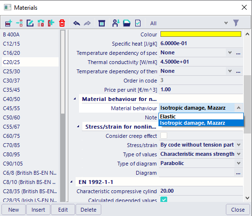
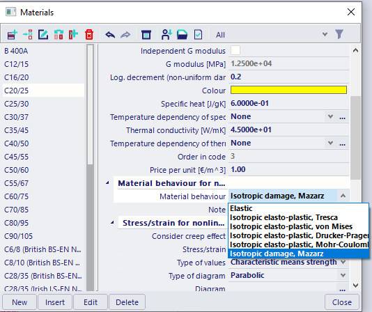
There is possibility to define Material behaviour for nonlinear analysis of the concrete and reinforcement, if functionality General plasticity or RC material nonlinearity or SFRC material nonlinearity is ON . Depending on selected functionality, there is possible to define different material behaviour for nonlinear analysis
Material behaviour for the concrete or steel fibre concrete
| RC/SFRC material nonlinearity | General plasticity && RC/SFRC material nonlinearity |
|
|
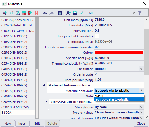
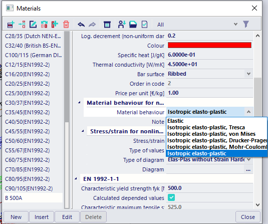
Material behaviour for the reinforcement
| RC/SFRC material nonlinearity | General plasticity && RC/SFRC material nonlinearity |
|
|
Material behaviou for plasticity of the concrete and reinforcement is described in "General plasticity"
Material diagrams of the concrete
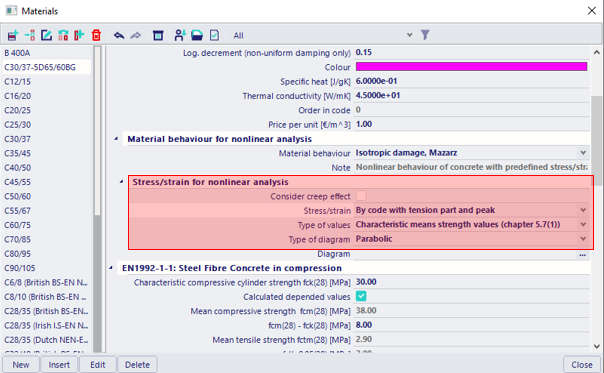
When material behaviour of the concrete is set to "Isotropic damage, Mazarz", then there is possible to define stress-strain diagram of the concrete for nonlinear analysis. There is possible to use some predefined stress-strain diagram or to create own stress/strain diagram.
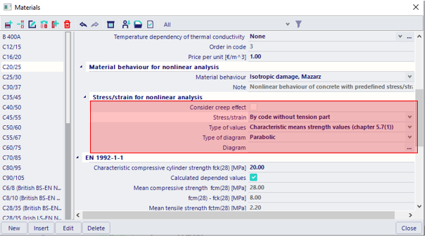
There are four types of stress/strain diagram (combo box Stress/strain)
- By code without tension part
- By code with tension part
- By user definition - when this is selected then user can define its own stress/strain diagram
User is able to select which value will be used for creating the stress-strain diagram (combo box Type of values)
- characteristic means strength value (chapter 5.7.(1)) - these values should be used for analysis serviceability limit state , it means for calculation crack width and deflection
- design values ( chapter 5.8.6(3)) - these values should be used for analysis ultimate limit state
There are also two option for definition of diagram for non-linear calculation for concrete in compression (combo box Type of diagram)
- parabolic
- linear-constant
And additionally its possible to consider creep effect (check box Consider creep effect)
- if check box is ON, then creep is taken into account for analysis (see clause 5.8.6(4) in EN 1992-1-1), it means all strains in stress-strain diagram is multiplied by coefficient (1+j), where value j is defined in property Creep factor(phi)
The shape of stress-strain diagram can be presented in dialog by clicking on button Diagram
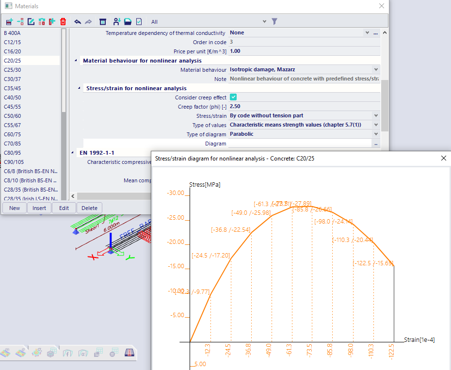
Predefined concrete diagram have ends of diagram for tensile and compressive part defined as failure (it means the stress goes to zero without increasing of strain). Ends diagrams is presented in picture of diagram by grey colour
User definition is possible if Stress/strain = By user definition. There is possible to define own stress/strain diagram in dialog User definition. There is possible to define diagram
- by inserting points with stress and strain via using buttons (Insert, delete, clear )in pop menu (by right clicking mouse on table with points)
- by pasting of the diagram from clipboard (from txt, xls files...) via using button Paste all in pop menu (by right clicking mouse on table with points)
- by creating from default via button Create from default... , where Stress/strain, Type of values, Type of diagram, Consider creep effect has to be defined
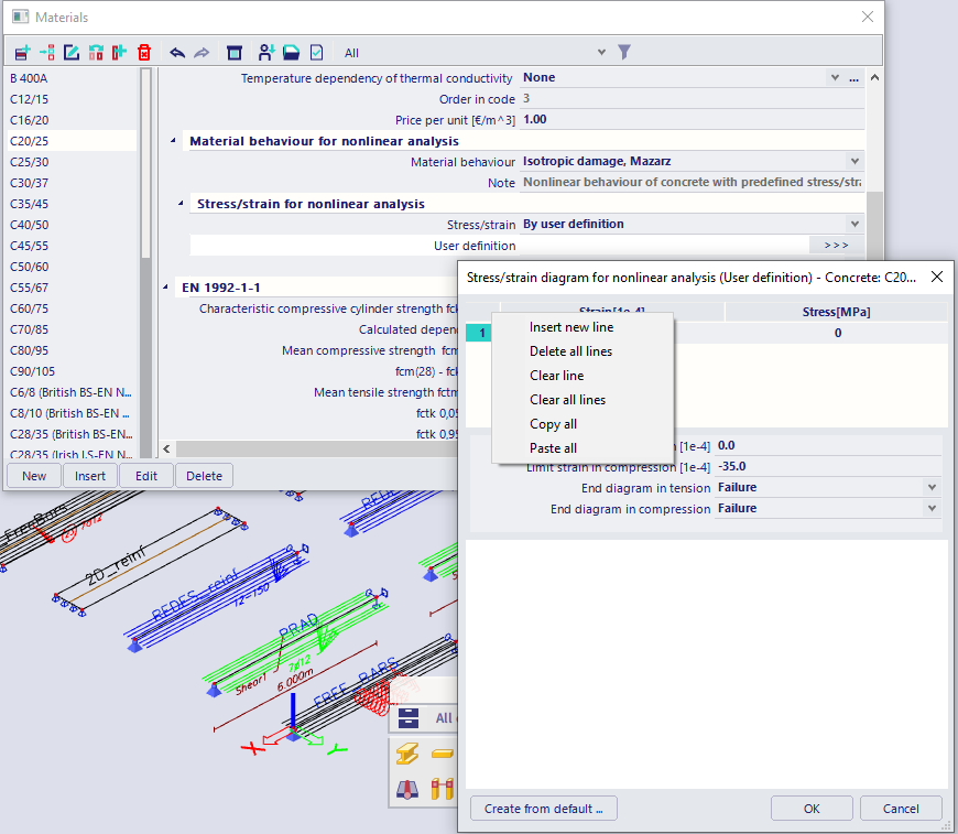
Except for definition of point , there is necessary to defined limit strain for diagram in tension and compression and Ends of diagram in tension and compresion. There are supported following ends:
- failure -the stress goes to zero without increasing of strain
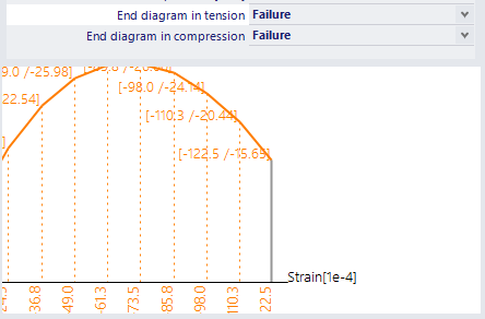
- yielding - the strain is increased without increasing of stress
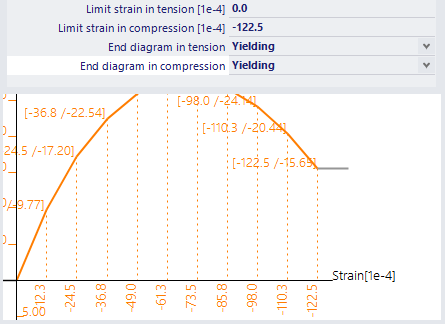
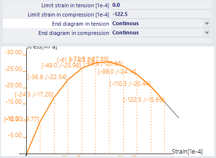
- continuous - the strain and stress is increased along the line from last two points of diagram
Material diagrams of the steel fibre concrete
When material behaviour of steel fibre concrete is set to "Isotropic damage, Mazarz", then there is possible to define stress-strain diagram of the steel fibre concrete for nonlinear analysis. There is possible to use some predefined stress-strain diagram or to create own stress/strain diagram.
There are four types of stress/strain diagram (combo box Stress/strain)
- By code without tension part
- By code with tension part and peak
- By code with tension part and without peak
- By user definition - when this is selected then user can define its own stress/strain diagram
User is able to select which value will be used for creating the stress-strain diagram (combo box Type of values)
- characteristic means strength value (chapter 5.7.(1)) - these values should be used for analysis serviceability limit state , it means for calculation crack width and deflection
- design values ( chapter 5.8.6(3)) - these values should be used for analysis ultimate limit state
There are also two option for definition of diagram for non-linear calculation for concrete in compression (combo box Type of diagram)
- parabolic
- linear-constant
And additionally its possible to consider creep effect (check box Consider creep effect)
- if check box is ON, then creep is taken into account for analysis (see clause 5.8.6(4) in EN 1992-1-1), it means all strains in stress-strain diagram is multiplied by coefficient (1+j), where value j is defined in property Creep factor(phi)
The shape of stress-strain diagram can be presented in dialog by clicking on button Diagram
Predefined steel fibre concrete diagram have ends of diagram for tensile and compressive part defined as failure (it means the stress goes to zero without increasing of strain). Ends diagrams is presented in picture of diagram by grey colour.
User definition is possible if Stress/strain = By user definition. There is possible to define own stress/strain diagram in dialog User definition. The definition is simila as for concrete,see definition of user diagram for the concrete
Material diagrams of the reinforcement
When material behaviour of the reinforcement is set to "Isotropic -elasto plastic", then there is possible to define stress-strain diagram of the reinforcement for nonlinear analysis. There is possible to use some predefined stress-strain diagram or to create own stress/strain diagram.
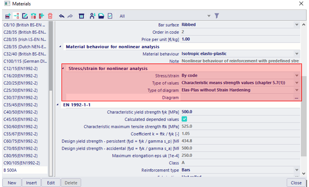
There are four types of stress/strain diagram (combo box Stress/strain)
- By code
- By user definition - when this is selected then user can define its own stress/strain diagram
User is able to select which value will be used for creating the stress-strain diagram (combo box Type of values)
- characteristic means strength value (chapter 5.7.(1)) - these values should be used for analysis serviceability limit state , it means for calculation crack width and deflection
- design values ( chapter 5.8.6(3)) - these values should be used for analysis ultimate limit state
There are also two option for definition of diagram for non-linear calculation for concrete in compression (combo box Type of diagram)
- Elasto-plastic without strain hardening
- Elasto-plastic with strain hardening
And additionally its possible to consider creep effect (check box Consider creep effect)
- if check box is ON, then creep is taken into account for analysis (see clause 5.8.6(4) in EN 1992-1-1), it means all strains in stress-strain diagram is multiplied by coefficient (1+j), where value j is defined in property Creep factor(phi)
The shape of stress-strain diagram can be presented in dialog by clicking on button Diagram
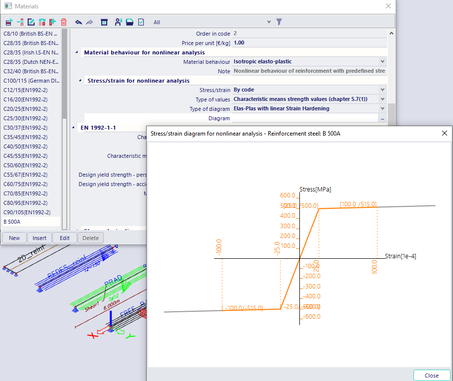
Predefined reinforcement diagram have ends of diagram for tensile and compressive part defined as continuous ( the strain and stress is increased along the line from last two points of diagram). Ends diagrams is presented in picture of diagram by grey colour
User definition is possible if Stress/strain = By user definition. There is possible to define own stress/strain diagram in dialog User definition. There is possible to define diagram
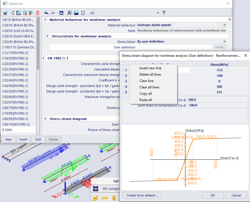
- by inserting points with stress and strain via using buttons (Insert, delete, clear )in pop menu (by right clicking mouse on table with points)
- by pasting of the diagram from clipboard (from txt, xls files...) via using button Paste all in pop menu (by right clicking mouse on table with points)
- by creating from default via button Create from default... , where Type of values and Type of diagram has to be defined
Except for definition of point , there is necessary to defined limit strain for diagram in tension and compression. Ends of diagram in tension and compression is automatically set to continuous (the strain and stress is increased along the line from last two points ).