6 Evaluation of internal forces
The internal forces can be evaluated in the Results > 2D members > Member 2D - Internal forces and also in Concrete Advanced > 2D member > Member design > Internal forces ULS. Basic magnitudes are the same for both cases, but the differences are in the Elementary design magnitudes. There are several differences between those internal forces. Explanation about details is described in [5]. The short overview of differences is summarized in the following table.
|
Results |
Concrete |
|
|---|---|---|
|
ENV method "2D Concrete design - EC2; SCIA CZ, s.r.o, Prague 2011" |
NEDIM (Baumann theory) |
|
|
Design magnitudes in the direction of the local axis (X, Y) of the slab |
YES |
NO |
|
Design magnitudes in the direction of the reinforcement |
NO |
YES |
|
Taking into account torsional moment mxy |
YES |
YES |
|
Shear effect (6.2.3(7)) |
NO |
YES |
The design elementary magnitudes are the same in Results and Concrete part only if the following settings are fulfilled:
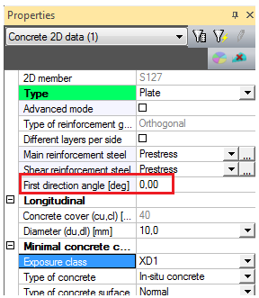
- Two directions of perpendicular reinforcement
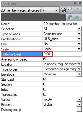
- The first direction angle in Concrete 2D member data is the same as the rotation in Results > 2D Internal forces service.
|
Concrete > 2D member > Member data |
Results > 2D Internal forces |
|---|---|
|
|
|
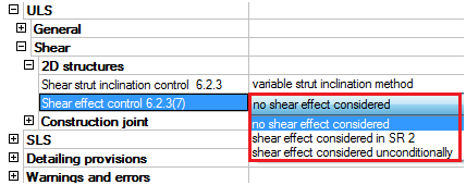
- Shear effect is not taken into account in Concrete setup > ULS > Shear > 2D structures
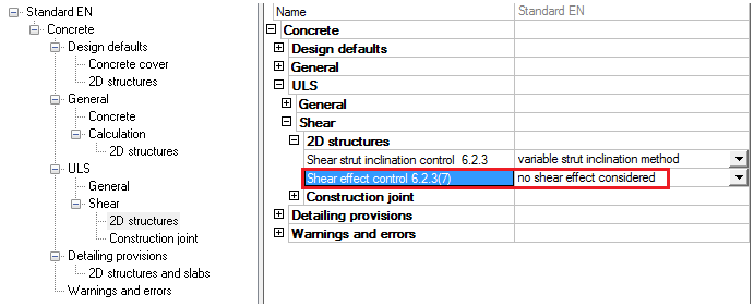
Fig. 36 Concrete setup for shear in 2D structures
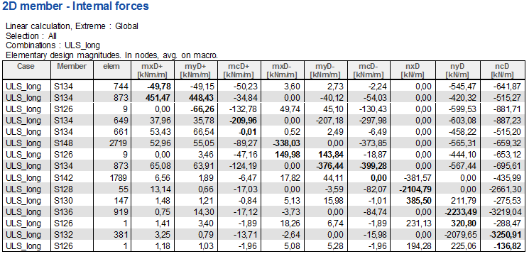
6.1 Elementary design magnitudes - results
Elementary design magnitudes in Results are calculated according to a different method (ENV method) and the internal forces are recalculated to directions of the local axes (x, y) of the 2D element instead of to the direction of the reinforcement as it is done for the design internal forces in Concrete. These internal forces cover also torsion mxy but they are not taking into account the additional tensile forces from shear. These design internal forces are only for the presentation and they are not used for the design of reinforcement. The internal forces in Concrete, which are recalculated into the direction of the reinforcement, are used for the design.
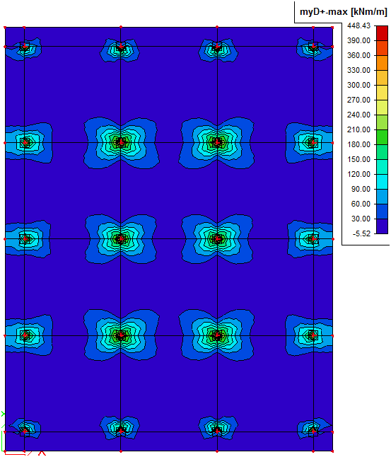
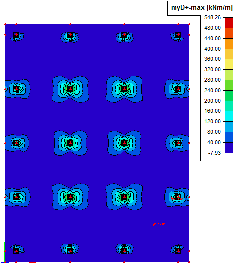
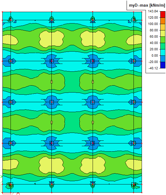
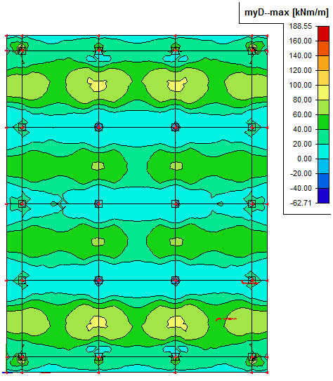
We can compare the results from the model where prestressing is modelled using the real tendon with the model where the equivalent load is used. You can see the results in the tables below. Because the internal forces are higher for the model with the real tendon probably the short term losses of 10% were overestimated in comparison with the real calculation of short term losses in the model with the real tendon.
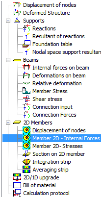
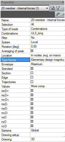
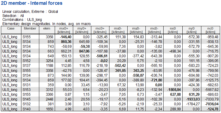
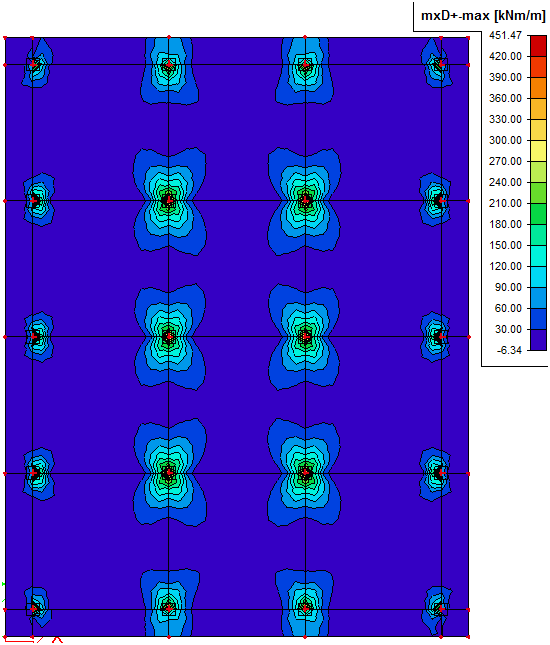
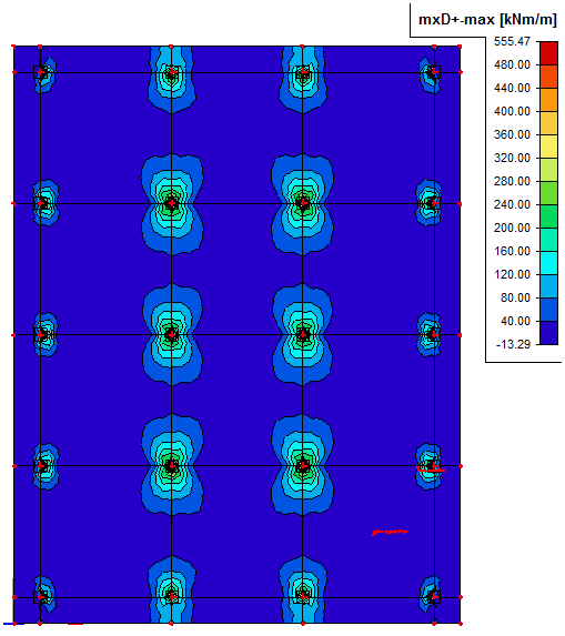
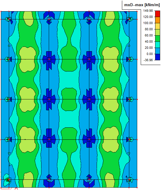
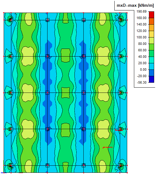
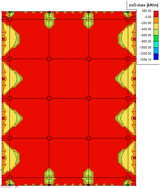
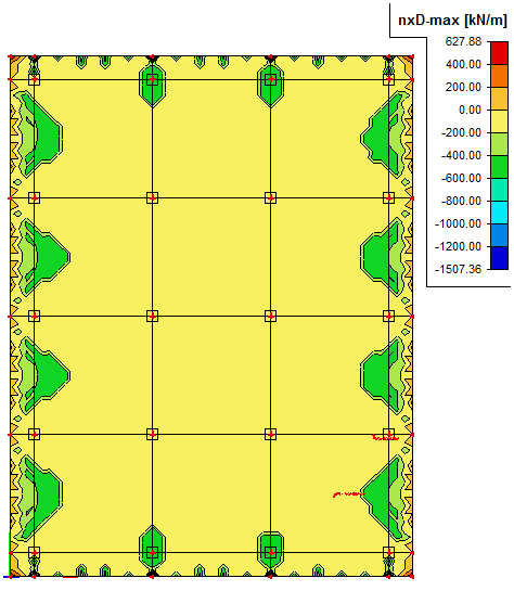
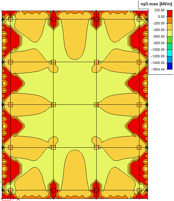
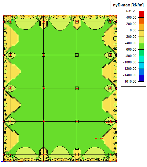
Fig. 37 Elementary design magnitudes - results
Description of the values above:
mxD+, mxD-
Design bending moment in the x direction of LSS at the lower surface (-) or upper surface (+)
myD+, myD+
Design bending moment in the y direction of LSS at the lower surface (-) or upper surface (+)
nxD+, nxD-
Design normal force in x direction of LSS at the lower surface (-) or upper surface (+)
nyD+, nyD-
Design normal force in the y direction of LSS at the lower surface (-) or upper surface (+)
mcD+, mcD-
Design bending moment in the compressive strut at lower surface (-) or upper surface (+) which have to be transferred by concrete
ncD-, ncD+
Design normal force in the compressive strut at lower surface (-) or upper surface (+) which have to be transferred by concrete
|
Model |
Output table |
|---|---|
|
Equivalent load |
|
|
Real tendon |
|
|
Equivalent load |
Real tendon |
|
|---|---|---|
|
mxD+ |
|
|
|
mxD- |
|
|
|
myD+ |
|
|
|
myD- |
|
|
|
nxD |
|
|
|
nyD |
|
|
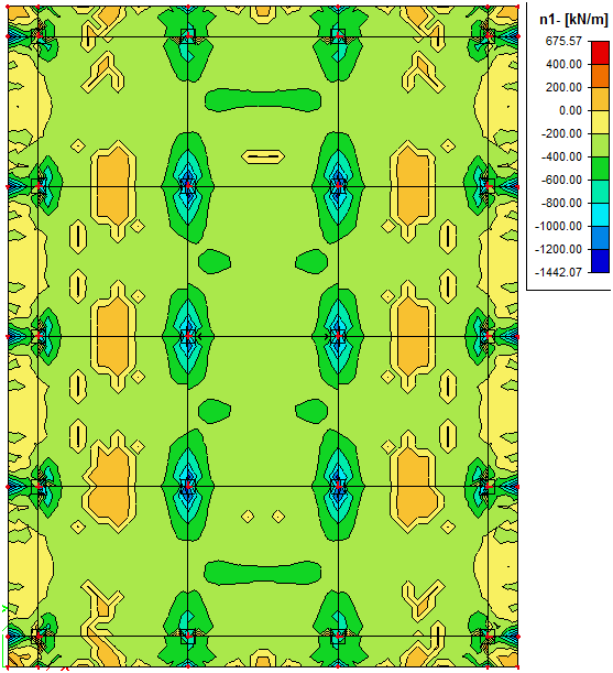
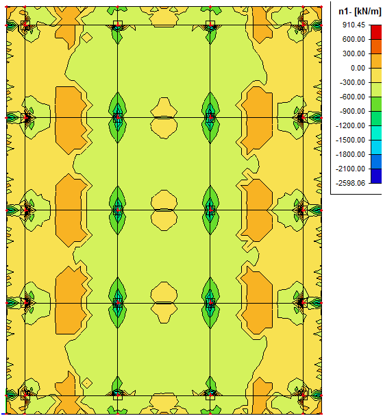
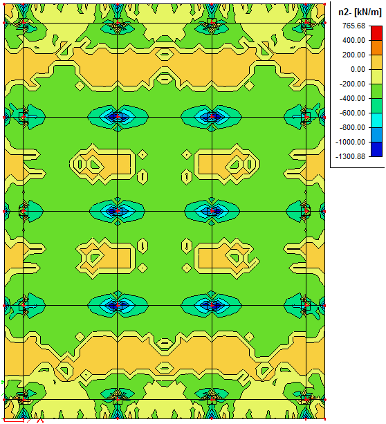
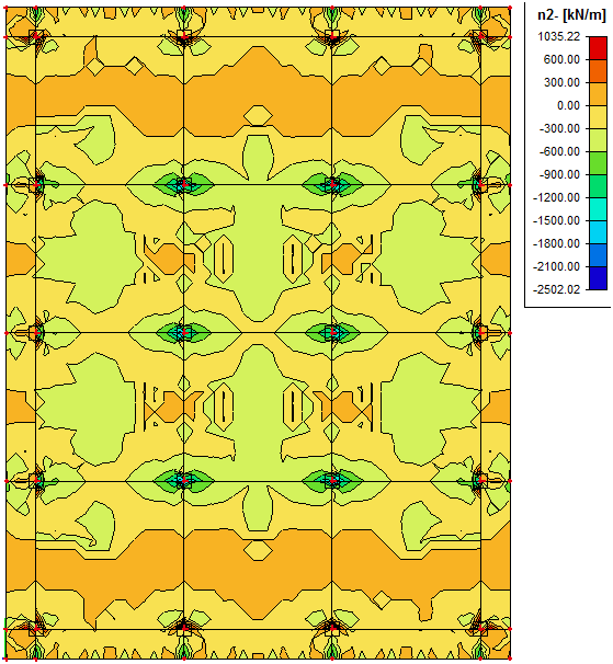
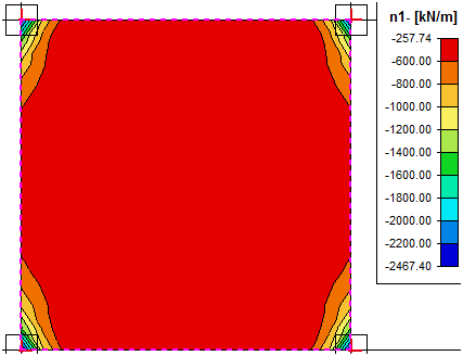
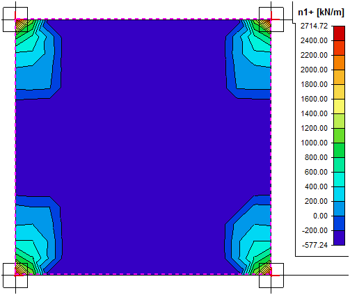
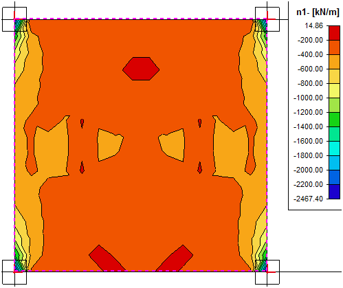
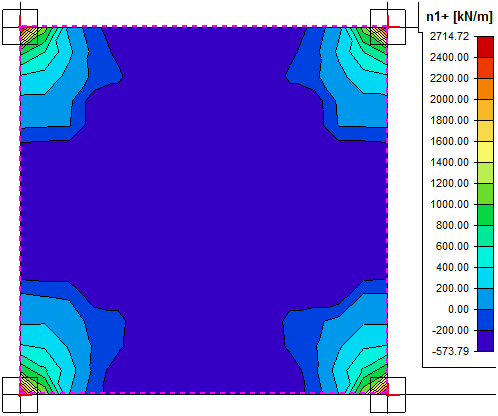
6.2 Elementary design magnitudes – concrete
These internal forces are recalculated into the direction of reinforcement. Also torsional moment mxy and shear effect are taken into account with respect to the settings in the concrete setup (see "6.3 Shear effect during design of reinforcement")
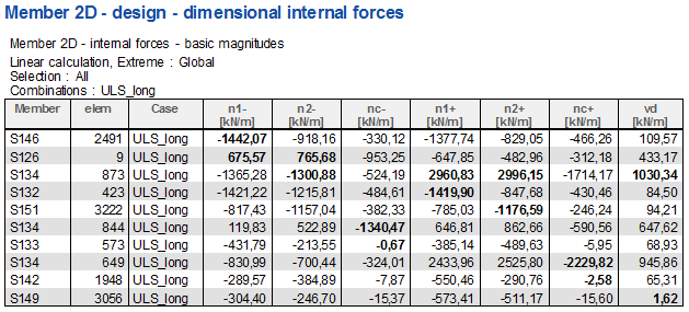
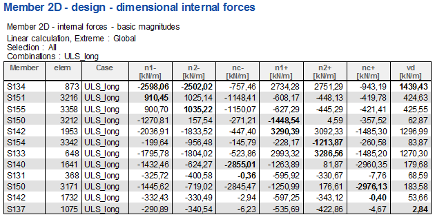
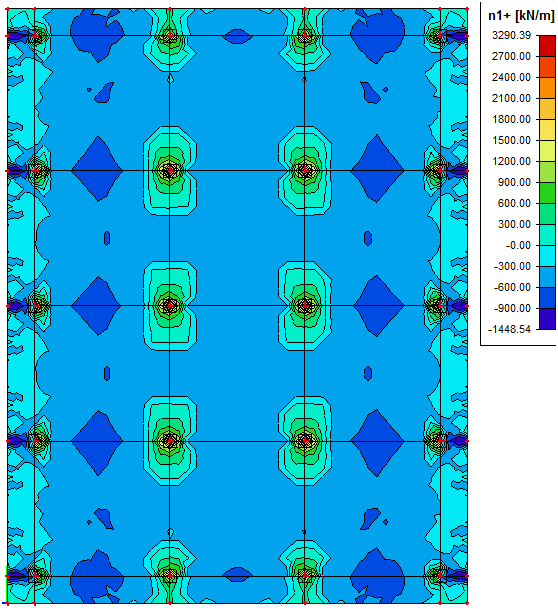
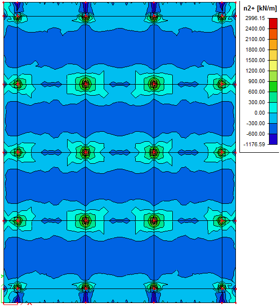
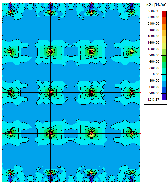
Again we can compare the results from the model where prestressing is modelled using the real tendon with the model where the equivalent load is used. The structure is of type General XYZ (see project data). Only normal design forces (n1-; n1+; n2-; n2+) are available for this type of structure.
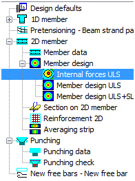
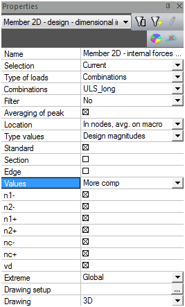
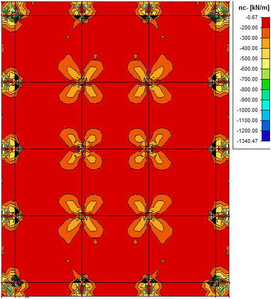
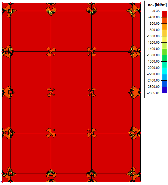
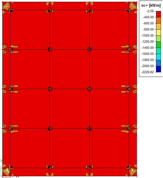
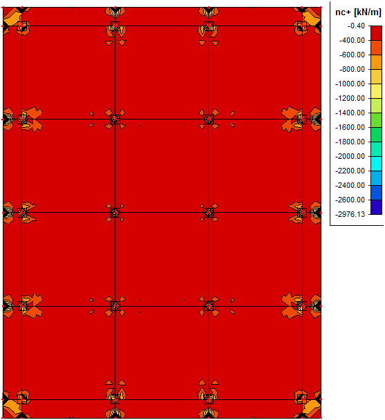
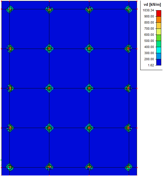
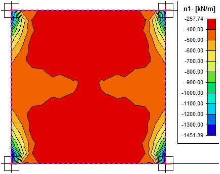
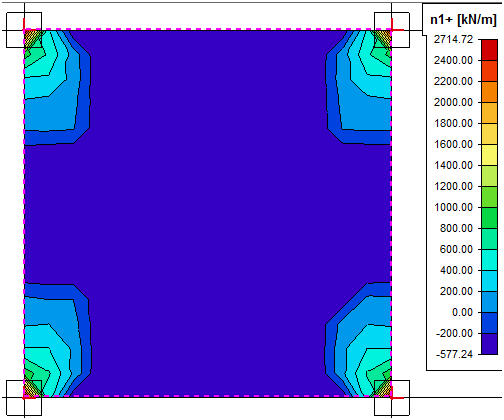
Fig. 38 Elementary design magnitudes – concrete
Description of the values above:
n1-,n2-,n3-,n1+,n2+,n3+
Design normal force in reinforcement direction 1, 2 and 3 for lower surface (-) or upper surface (+). These values are used for reinforcement design
nc-, nc+
Design normal force in concrete compression strut for lower surface (-) or upper surface (+) which must be covered by concrete. If the concrete strut is not able to cover this force, the design will end up with error message
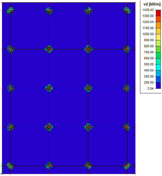
vd
Resultant shear force which is perpendicular to the 2D member plane.
The results mentioned below are evaluated for combination ULS_long and they have covered the shear effect in SR2.
|
Model |
Output table |
|---|---|
|
Equivalent load |
|
|
Real tendon |
|
|
Equivalent load |
Real tendon |
|
|---|---|---|
|
n1- |
|
|
|
n2- |
|
|
|
n1+ |
|
|
|
n2+ |
|
|
|
nc- |
|
|
|
nc+ |
|
|
|
vd |
|
|

6.3 Shear effect during design of reinforcement
As mentioned above, dimensional magnitudes are recalculated into the reinforcement directions. Moreover torsion moment mxy is also taken into account in these values. It is also possible to calculate with the influence of tension force caused by shear stress. This can be set in Concrete setup dialog with attribute Shear effect control 6.2.3(7), under Concrete Advanced > ULS > Shear > 2D structures. This attribute can be set in three ways:
- No shear effect considered (tension force from shear stress will not be considered in calculation of design forces)
- Shear effect considered in SR2 (tension force from shear stress will be considered in the calcuation of design forces only in elements where shear force is not covered by the concrete capacity, i.e. in elements where shear reinforcement is needed)
- Shear effect considered unconditionally (tension force from shear stress will be considered in the calculation of design forces in all elements, regardless whether the shear reinforcement is or is not needed)
The recommended option is to take the shear effect into account only in SR2.
The comparison of the shear effect on the results for Elementary design forces and Design ULS+SLS is performed for model with the real tendon and only for slab S138 in the following two tables.
|
Type |
n1- |
n1+ |
|---|---|---|
|
No shear effect |
|
|
|
Shear effect in SR2 |
|
|
|
Shear effect unconditionally |
|
|
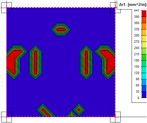
From the table above it is clear that the shear effect has the main influence only on design magnitudes for design of the lower reinforcement.
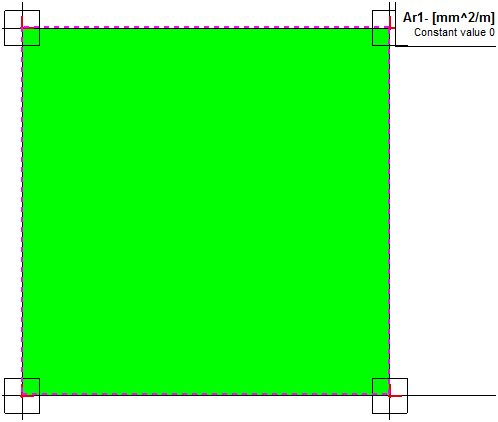
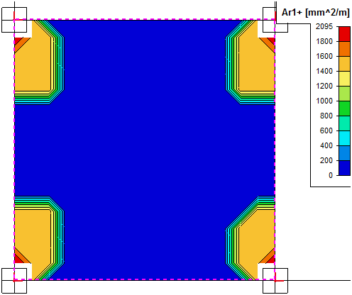
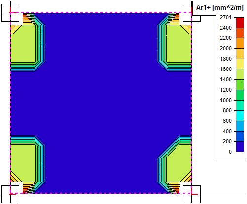
|
Type |
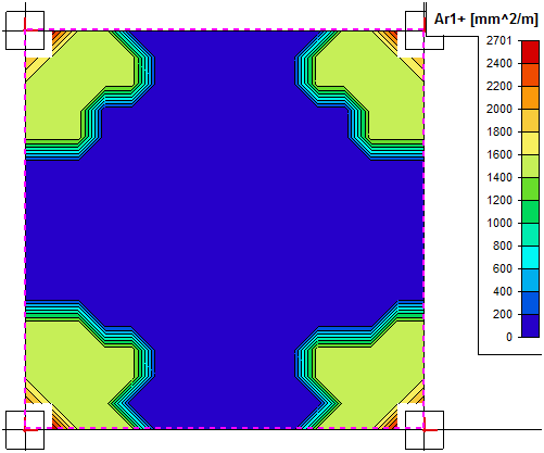
Ar1- |
Ar1+ |
|---|---|---|
|
No shear effect |
|
|
|
Shear effect in SR2 |
|
|
|
Shear effect unconditionally |
|
|