Stress limitation theoretical background
Stress limitation check is based on the calculation of stresses in particular component (concrete edge or reinforcement bar) in the principal direction of internal forces and on the comparison with limited values with respect of [2] EN1992-1-1 requirements. Based on the internal forces, concrete cross-section and reinforcement defined by the user, SCIA Engineer is able to calculate the plain of equilibrium of a 2D and find the actual value of stresses in each component. The stresses are calculated on the same internal forces as are used for crack width. For more information about recalculation of internal forces and reinforcement, see "Crack width theoretical background".
Two states are checked in the stress limitation check.
- Compressive stress in concrete - The high value of compressive stress in concrete could lead to appearance of longitudinal cracks, spreading of micro-cracks in concrete and higher values of creep (mainly non-linear). This effect can lead to state when the structure is unusable.
- Tensile stress in reinforcement - The stress in reinforcement is verified due to limitation of unacceptable strain existence and thus appearance of cracks in concrete in case of standard reinforcement exists only. Stress in reinforcement is evaluated only when cracks appear (generally tensile stress in concrete σs is greater than mean tensile strength of concrete fctm).
In case of NEN NA the value of stress in reinforcement is calculated but not checked due to fact it is not required in NEN-NA.
The linear elastic stress-strain diagram on the serviceability limit state is used for the finding of the plane of the equilibrium.
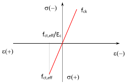
The following assumptions are used:
- There are used stress-strain diagrams which are defined in properties of material.
- Concrete - linear stress-strain diagram dependent on:
- Type of elasticity modulus - short-term (Ec) or long-term (Ec,eff) elasticity modulus
- Cracking of the cross-section
- un-cracked cross-section - stress-strain diagram with tensile concrete
- cracked cross-section - stress-strain diagram without tensile concrete
- Reinforcement - linear stress-strain diagram with tensile branch (if reinforcement is presented in the 2D member)
Cracking status
The evaluation of tensile stress in reinforcement depend on the cracking status (appearance of the cracks).
Two possibilities are available according to chapter 7.1(2) in [2] EN1992-1-1
- 0 MPa - The first crack appears when tensile stress occurs in the cross-section
- fct,eff - The first crack appears when the tensile effective strength of concrete is reached in the cross-section
If cracks does not appear, the stress in reinforcement is not evaluated.
If cracks appear, the stress in reinforcement is evaluated and stress-strain diagram without tensile branch is considered for concrete.
Verification of concrete stress under characteristic load
Verification of concrete stress under characteristic load according to chapter 7.2(2) in [2] EN1992-1-1.
The verification is calculated against to longitudinal cracks in concrete and it is provided only for exposure classes XD, XF and XS. Generally, maximal compressive concrete stress σc,char has to be lesser than maximal allowed compressive concrete strength for characteristic combination σc,char,lim. It can be expressed as follows:
σc,char ≤ σc,char,lim = k1 ∙ fck
where
| k1 |
The factor for maximum compressive stress in concrete under SLS characteristic combination |
| fck |
Characteristic compressive cylinder strength of concrete at 28 days |
Verification of concrete stress under quasi-permanent load
Verification of concrete stress under quasi-permanent load according to chapter 7.2(3) in EN 1992-1-1.
The verification is calculated against to considering of linear creep only. When the condition is not fulfilled then non-linear creep calculation should be considered. Generally, maximal compressive concrete stress σc,qp has to be lesser than maximal allowed compressive concrete strength for quasi-permanent combination σc,qp,lim.It can be expressed as follows:
σc,qp ≤ σc,qp,lim = k2 ∙ fck
where
| k2 |
The factor for maximum compressive stress in concrete under SLS quasi-permanent combination |
| fck |
Characteristic compressive cylinder strength of concrete at 28 days |
Verification of reinforcement stress under characteristic load
Verification of reinforcement stress under characteristic load according to chapter 7.2(5) in [2] EN1992-1-1.
The verification is calculated in case standard reinforcement exist only and it is against to considering of unacceptable cracks and deformation in the concrete. Generally, maximal tensile reinforcement stress σs,char has to be lesser than maximal allowed tensile reinforcement strength for characteristic combination σs,char,lim. It can be expressed as follows:
σs,char ≤ σs,char,lim = k3 ∙ fyk
When stress in reinforcement is caused by an imposed deformation, than factor k4 is used:
σs,char ≤ σs,char,lim = k4 ∙ fyk
where
| k3 |
The factor for maximum tensile stress in reinforcement under SLS characteristic combination |
| k4 | The factor for maximum tensile stress in reinforcement under SLS characteristic combination for imposed deformation |
| fck |
Characteristic compressive cylinder strength of concrete at 28 days |
Unity check
Final unity check is calculated from partial unity checks from all verifications.
UC = max(σc,char / σc,char,lim; σc,qp / σc,qp,lim; σs,char / σs,char,lim)