Adjusting the view
SCIA Engineer offers a wide range of functions to adjust the required view. Using the NaviCube is the preferred method, however, some more advanced possibilities are also listed below.
Using the NaviCube
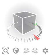
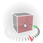
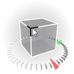

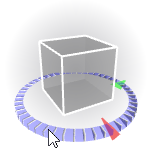
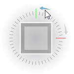


Mouse controlled adjustment of the view
In addition to the NaviCube, SCIA Engineer offers also a set of fast-access functions for the view adjustment.
|
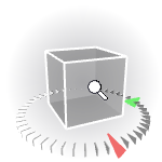
Zoom in/out |
- Use the mouse wheel - Press [Ctrl] and [Shift] keys simultaneously and hold them down. Then press the right mouse button and hold it down as well. Move the mouse up or down over the pad. |
|
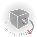
- Press [Ctrl] key and hold it down. Then press the right mouse button and hold it down as well. Move the mouse over the pad in order to get the required view direction. |
|
|
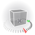
Pan |
- Press and hold the middle mouse button and move the mouse - Press [Shift] key and hold it down. Then press the right mouse button and hold it down as well. Move the mouse over the pad in order to get the required position of the structure on the screen. |
|
Zoom All |
Double-click the middle-button of your mouse to invoke function Zoom All. |
Rotation of view
The centre of rotation depends on initial conditions.
Menu functions for adjustment of the view
This mode of navigation is still available through the menu and, in some cases, the context menu. However it is deprecated and will ultimately be removed completely.
|
View > ZOOM > Zoom + |
Zooms in. |
|
View > ZOOM > Zoom - |
Zoom out. |
|
View > ZOOM > Zoom Cut-out |
Requires to define a cut-out for the zoom. The cut-out is then magnified in order to fit into the whole area of the graphical window. Once the function is started the mouse cursor changes. Position it to the upper left corner of the cut-out. Press the left mouse button and hold it down. Drag the mouse to place the cursor to the bottom right corner of the cut-out. Release the button. |
|
View > ZOOM > Zoom All |
Zoom in or out in order to fit the whole structure into the whole area of the graphical window. |
|
View > ZOOM > Zoom All – Selection |
Zoom in or out in order to fit the selected entities into the whole area of the graphical window. |
|
View > View > View X |
Adjusts the view in such a way so that the structure is viewed from the positive X-axis direction. Simultaneously zooms in or out to fit the whole structure into the whole area of the graphical window. |
|
View > View > View Y |
Adjusts the view in such a way so that the structure is viewed from the positive Y-axis direction. Simultaneously zooms in or out to fit the whole structure into the whole area of the graphical window. |
|
View > View > View Z |
Adjusts the view in such a way so that the structure is viewed from the positive Y-axis direction. Simultaneously zooms in or out to fit the whole structure into the whole area of the graphical window. |
|
View > View > View AXO |
Sets the view point vector to (1, -1, 1). Simultaneously zooms in or out to fit the whole structure into the whole area of the graphical window. |
Toolbar functions for adjustment of the view
This mode of navigation is deprecated. However, it is still can be usedby customizing the toolbars or using the Full set of toolbars instead of the standard set.
Functions for the adjustment of the view are arranged on toolbar View.
![]()
|
View in direction X |
Adjusts the view in such a way so that the structure is viewed from the positive X-axis direction. Simultaneously zooms in or out to fit the whole structure into the whole area of the graphical window. |
|
View in direction Y |
Adjusts the view in such a way so that the structure is viewed from the positive Y-axis direction. Simultaneously zooms in or out to fit the whole structure into the whole area of the graphical window. |
|
View in direction Z |
Adjusts the view in such a way so that the structure is viewed from the positive Y-axis direction. Simultaneously zooms in or out to fit the whole structure into the whole area of the graphical window. |
|
View in direction AXO |
Sets the view point vector to (1, -1, 1). Simultaneously zooms in or out to fit the whole structure into the whole area of the graphical window. |
|
Zoom in |
Zooms in. |
|
Zoom out |
Zooms out. |
|
Zoom by cut-out |
Requires to define a cut-out for the zoom. The cut-out is then magnified in order to fit into the whole area of the graphical window. Once the function is started the mouse cursor changes. Position it to the upper left corner of the cut-out. Press the left mouse button and hold it down. Drag the mouse to place the cursor to the bottom right corner of the cut-out. Release the button. |
|
Zoom all |
Zoom in or out in order to fit the whole structure into the whole area of the graphical window. |
|
Zoom all – selection |
Zoom in or out in order to fit the selected entities into the whole area of the graphical window. |
Window scroll-bar wheel-like buttons for adjustment of the view
This mode of navigation is deprecated. It is available only in case hardware OpenGL rendering is disabled (see "Environment settings").
Each graphical window has got three wheel-like buttons on the scroll-bar. If the scroll-bar is visible the "wheels" may be used to adjust the required view. The function of the three wheel-like buttons is:
|
Zoom (located on the bottom scroll-bar) |
Zooms in or out. |
|
Rotate horizontally (located on the bottom scroll-bar) |
Rotates the structure around the vertical axes (i.e. vertical axis of the screen). |
|
Rotate vertically (located on the right hand side scroll-bar) |
Rotates the structure around the horizontal axes (i.e. horizontal axis of the screen). |
The operation of the wheel-like buttons is simple. Just place the mouse cursor over the "wheel", press the left mouse button, hold it down and "turn the wheel" with left-right, or up-down, movement of the mouse over the pad.