Drawing of input data with eccentricity
Terminology
system line
The line inputted by the user, it has nodes at its ends.
eccentricity of beam
The offset of a 1D member defined in the local coordinates of the 1D member. We have the eccentricity in y- and z-direction.
reference line
The reference line of a 1D member if obtained when the eccentricity is added to the system line. The reference line corresponds to the centroidal axis of the 1D member.
eccentricity of loads
The offset of the load (or we may say add-data in general) related to the reference line.
Current status
Recent versions of SCIA Engineer drew loads relatively to the system line of the corresponding 1D member. Consequently, users could not check their real position on the 1D members, which could result in the wrong interpretation of input data and also results as we have to realise that results are related to the reference line and not to the system lines.
A related topic is the drawing of surfaces (and reference lines) of 1D members with regard to Construction Stages (CS). Cross-sections could change their shapes over time (in general the shape may differ for every CS). This influences the position of the reference lines of 1D members in individual CS and, of course, it also influences the drawing of loads and results on 1D members.
Drawing of input data with the eccentricity taken into account
Loads
So far, the load was displayed on the system line of the 1D member. This was a correct solution only if the load was defined without any eccentricity and if the reference line (centroidal line) of the 1D member coincided with the system line (i.e. in the case of a straight 1D member the line connecting the end nodes of the 1D member). However, as soon as any eccentricity was introduced either to the 1D member or to the load, this display style became misleading.
The new solution is based on the principle that all the loads (and other displayed quantities such as hinges, and even results) are always displayed in their real position.
A few examples dealing with input data follows.
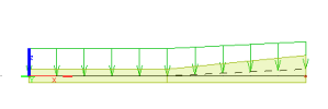
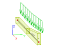
A 1D member with a one-side haunch subjected to a distributed load.
As you can see, the load follows the reference line (centroidal axis) of the 1D member.
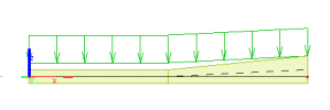
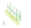
A 1D member with a one-side haunch subjected to an eccentric distributed load.
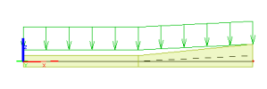
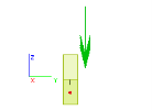
Here, the load acts on eccentricity defined in the z-direction. In the next picture, also the eccentricity in y-direction was introduced to the load.
When required, also a line showing the defined eccentricity of the load can be drawn. Thus, you can more easily see what the real action of the load is. In addition, in the case of several eccentrically loaded 1D members located close to each other, it will be unambiguous which load belongs to which 1D member.
The procedure to display the "eccentricity lines"
-
Open View parameters settings dialogue.
-
Select Tab Loads/Masses.
-
Tick option Display eccentricity.
-
Confirm with [OK].
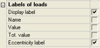
In addition to the "eccentricity lines", you can also display the magnitude of the specified eccentricity.
The procedure to display the eccentricity label
-
Open View parameters settings dialogue.
-
Select Tab Loads/Masses.
-
Tick option Labels of loads > Display label and Labels of loads > Eccentricity label.
-
Confirm with [OK].
Note: Loads are always drawn at their real location. View parameter Miscellaneous > Drawing style for Model+Loads > Show add data, results at has no effect on the loads.
Supports
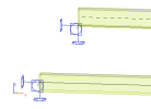
Let us have two beams supported at the end. One of the beams is defined with the system-line in the centre line of the beam. The second beam has the system line at the bottom surface.
The support is displayed where its real location in the calculation model is: (i) in the first case at the centre line of the beam, (ii) in the second case at the bottom edge of the beam.
Note: Supports are allways drawn at the system line of the beam. View parameter Miscellaneous > Drawing style for Model+Loads > Show add data, results at has no effect on the supports.
Hinges
Hinges, which also belong to additional data of the SCIA Engineer model, can also take into account possible eccentricity of the 1D member at which they are defined.
Unlike loads and supports however, hinges allow the user to decide on the drawing style.
The procedure to select the display mode
-
Open View parameters settings dialogue.
-
Select Tab Misc..
-
Set the option Drawing style for Model+Loads > Show add data, results at to:
-
Reference line in order to see the real position of the hinge (the hinge is put on a short rigid arm that is not drawn in the screen).
-
System line in order to see the schematic position of the hinge.
-
-
Confirm with [OK].
Results
Note: Results are always drawn in the system line. (Despite the specification, it was not done in this version.)
Structural model
Note: The display of eccentric entities relates exclusively to the analysis model. It has no relation to the structural shape.

