FEM - Hinges
Introduction
This chapter is to provide a closer information about the behaviour of hinges (how these are considered internally).
Hinge on 2D member edge and hinge on beam
How are hinges internally considered
Below, an example of how the hinges are currently (since SCIA Engineer version 20, 64 bit) considered is provided (this is not valid for version 19.1., where an old implementation of hinges is included).
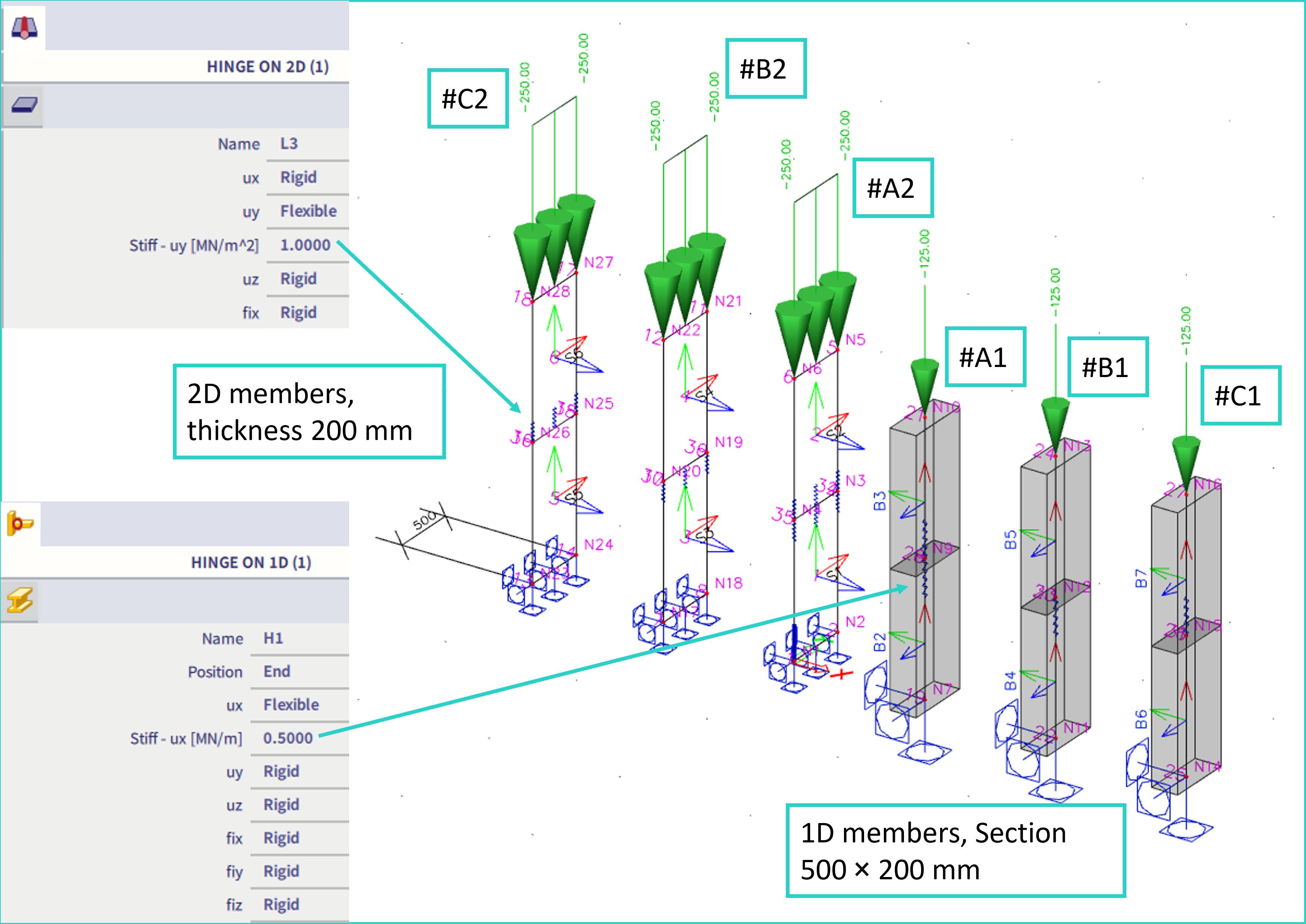
An example is provided using flexible hinge in one direction (translation along the axis of the column). Cases noted as #A1, #B1 and #C1 are 1D members, and cases noted #A2 - #C2 are 2D members (walls in this case). The line hinge stiffness and load of 2D members is set so it corresponds with the load and hinge stiffness applied on 1D members. In the cases #A1 and #A2, the hinge is modelled on both sides of the edge where the hinge is to be considered (this solution is not recommended). In the rest cases (#B, #C), the hinge is always modelled only on one side (what is recommended).
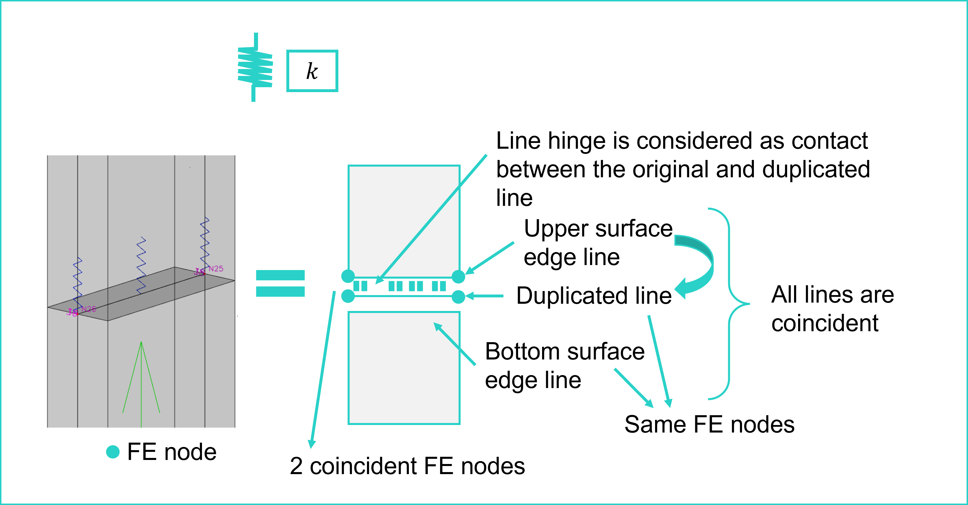
The internal consideration of the hinge for case #C2 is explained in the figure below (case #B2 is practically the same, and #C1 #B1 are for 1D members considered analogically). If the hinge is modelled at the edge of surface, that corresponding line is duplicated, and contact is internally defined between these two lines. All the lines are mutually coincident. The duplicated line contains the same finite element (FE) nodes as the other coincident edge line (which has no line hinge defined). Hence, in this case, along such edge, there are always 2 coincident FE nodes, as shown below:
However, when the line hinge is modelled on both edges, two duplicated lines are created, which share the same FE nodes. These FE nodes are however not attached to any 2D structural finite element. In some cases, this might cause singularity (not sufficiently constrained node) if the hinge is free (with 0 stiffness). In general it is not recommended to model hinge on all the possible coincident edges. Changing such free hinge to flexible with little stiffness will remove the possible singularity.
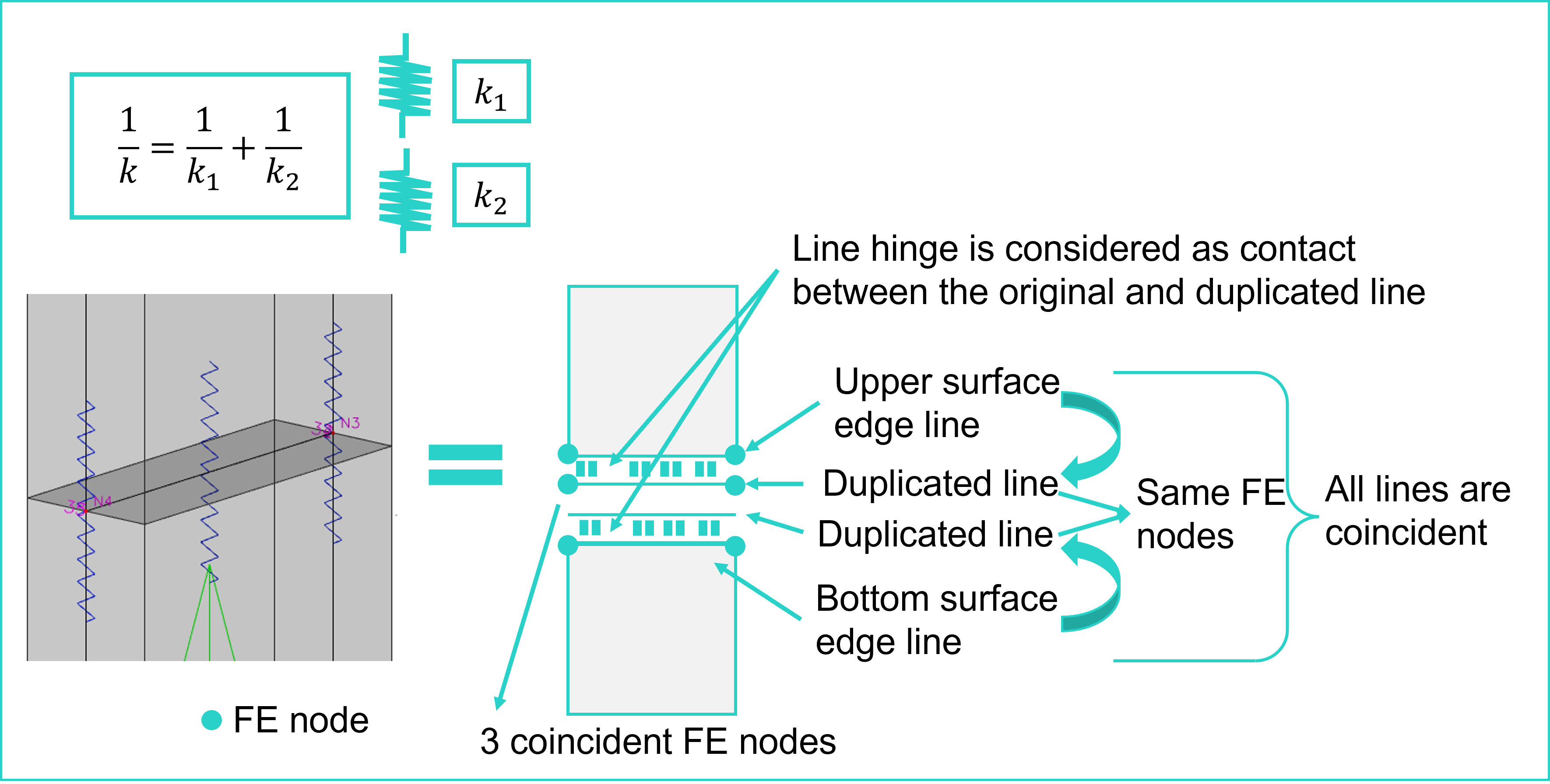
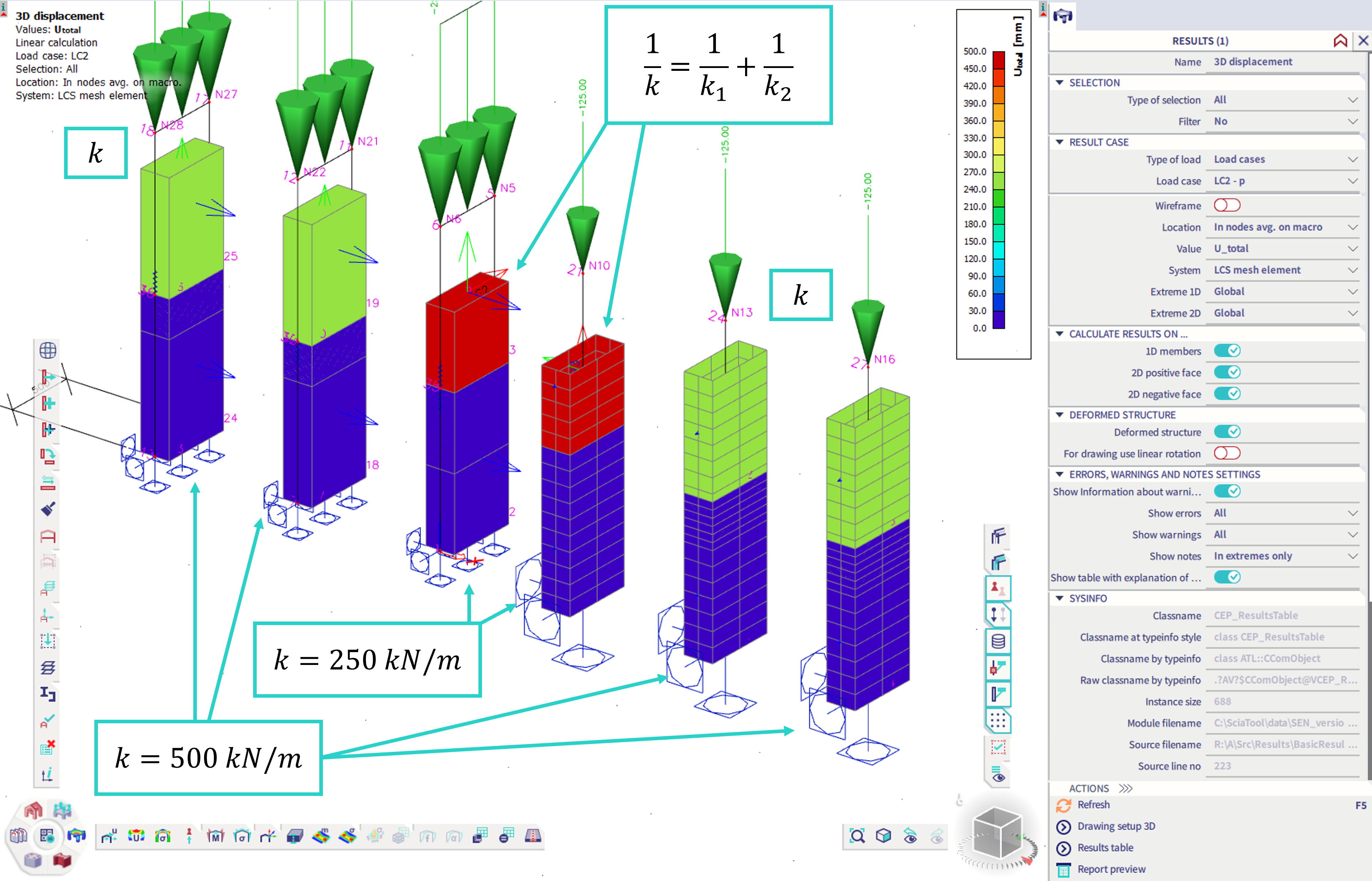
Also, user should be aware of the fact, that modelling 2 hinges in parallel, the resulting stiffness k is smaller then the stiffnesses of the single hinges (analogically for all the other possible hinge releases, like rotation etc.):
If more coincident edges from more 2D members meet in one line, it is recommended to keep at least one such edge without hinge. Analogically with more 1D members meeting in one point.
Note: The behaviour of line hinge at the surface edge was different in previous version (19.1.). In this version, no matter whether the line hinge of stiffness k was modelled on one edge, the other, or both (in case there are two coincident edges), and the total stiffness was considered as k, what was not correct from the structural mechanics point of view. However, the hinge on beam considered the stiffness as a resultant of in series stiffnesses.