Step 2: Set the ESA ID for each variable which needs to be linked
As demonstrated in the first example, upon executing the check from within SCIA Engineer, an export will be made of all relevant model data (cross-sections, materials, internal forces ...) to the 'DataCache'.
In this first step, the ESA ID's for the relevant variables which will be linked are defined in the Form.
Launch the SCIA Design Forms Builder and open the Form Manual_Example_2.CLS.
Step 2.1: Set the ID for the Input data
Within this Form, the grid on the 'Calculation' tab shows the double values to be manually inputted in a green color:
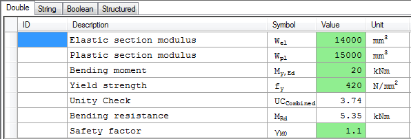
Compared to the first example, the additional parameter which can be obtained through the DataCache is the Plastic section modulus Wpl.
The safety factor γM0 however is a property which does not exist in the DataCache, so this will not be linked directly but set later on as Member data.
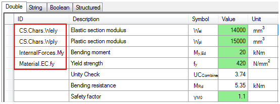
Using the basic information from Annex B the following ID's are found to represent the data needed by the form:
|
ESA ID |
Variable |
|---|---|
|
CS.Chars.Wely |
Elastic section modulus about the principal y-axis |
|
CS.Chars.Wply |
Plastic section modulus about the principal y-axis |
|
InternalForces.My |
Bending moment about the principal y-axis |
|
Material.EC.fy |
Yield strength of the material for Eurocode EC-EN |
These ID's are inputted within the grid of the Form:
This concludes the first part of this step; all input variables for the Form which can be obtained from the DataCache are now properly linked to ESA.ID's.
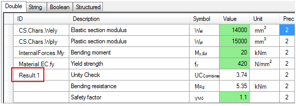
Step 2.2: Set the ID for the Output (Result) data
In this example there is one result value which will be defined, the Unity Check value UCCombined. This variable will thus be given the ID Result.1.
In order to let the Form take into account the ID's defined in this Step refresh the Form either by pressing the button  or the F5 key.
This concludes the definition of the in- and output variables.