Direct Analysis Method
The direct analysis method as described in chapter C of AISC 360-16 is explained below on how to do it within SCIA Engineer. In summary the following steps need to be followed:
-
Define the imperfections
-
Reduce the stiffness
-
Set the buckling factors to 1
-
Run nonlinear analysis and execute the steel code check
1) Define the imperfections
A global imperfection as specified in the commentary to C2.2 is applied on the structure in the form of:
-
Member out-of-straightness equal to L/1000, where L is the member length between brace or framing points.
-
Frame out-of-plumbness equal to H/500+H/1000, where H is the story height.
First a set of functionalities to enable to introduce these imperfections needs to be activated, activate the following functionalities:
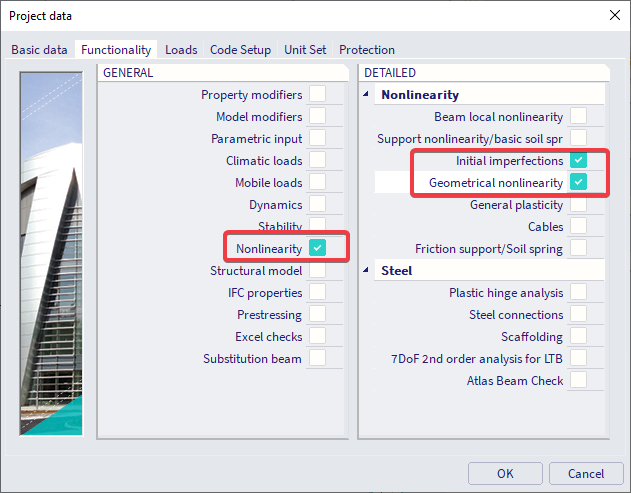
1.1) Member out-of-straightness
Bow imperfections can be used to introduce a member out-of-straightness of L/1000.
This can achieved choosing simple curvature in the nonlinear combinations with a value of 1/1000:

1.2) Frame out-of-plumbness
Global imperfections can be used to introduce the frame out-of-plumbness of H/500 + H/1000.
This can be achieved as follows:
Go to Libraries > Structure & analysis > Initial deformations

Define under the "Pos" column the height of the structure, and under "Defor" column the result of height divided by 333 (note 333 is the denominator when adding up 1/1000+1/500)

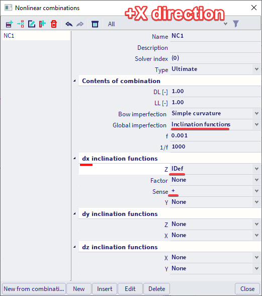
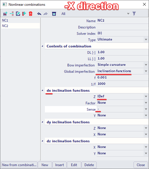
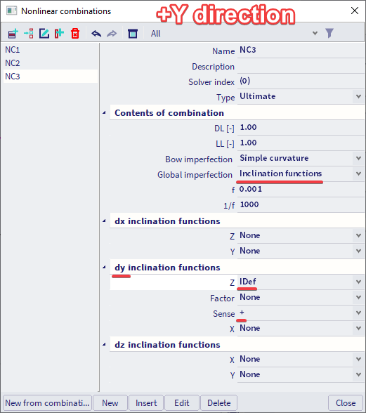
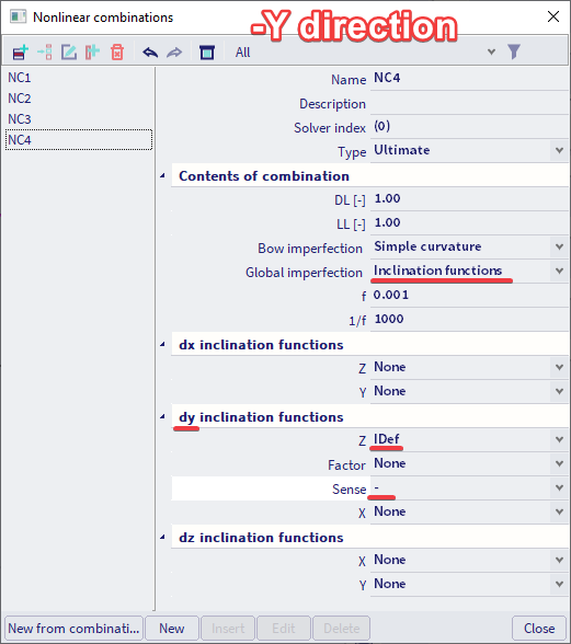
Next assign this inclination function to the nonlinear combinations in the 4 directions. This means that all your nonlinear combinations need to be duplicated in the 4 directions in order to assign for each set the inclination function in +X, -X, +Y and -Y direction of the global coordinate system.
2) Reduce the stiffness
According to AIS-360-16 all stiffnesses that contribute to the stability of the structure need to be reduced by a factor of 0.8.
This can be achieved by first activating the functionality "Property modifiers":

Next the reduction can be assigned to every applicable member by means of 1D property modifiers.

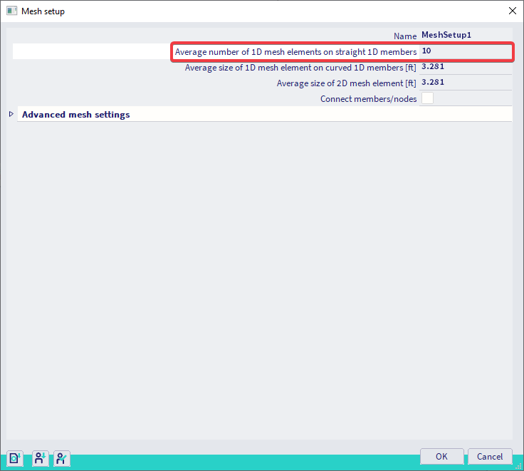
3) Refine the finite element mesh
In order to properly account for the 2nd order effects the number of mesh elements per member needs to be increased. A value higher than 3 is the bare minimum, a value of 10 or higher is advised in order to obtain accurate results. This can be done within the mesh settings as follows:
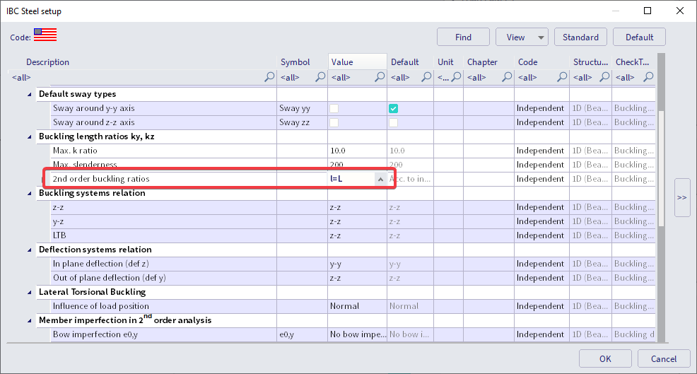
4) Set the buckling factors to 1
The buckling factor K should be set to 1.00, this can be done within the steel setup as follows:
5) Run nonlinear analysis and execute the steel code check
All necessary preparations for the 2nd order analysis have been performed.
Run a nonlinear analysis on your structure which is in fact a 2nd order analysis according to the Direct Analysis Method and execute afterwards the steel code check with the nonlinear combinations to validate your structure.