Lateral Torsional Buckling
The Lateral Torsional Buckling Check is executed according to EN 1993-1-1 art. 6.3.2.1.
CHS sections (Formcode 3) are taken as non-susceptible to Lateral Torsional Buckling.
RHS sections (Formcode 2) sections are classified as non-susceptible to Lateral Torsional Buckling if the following condition is fulfilled (Ref.[9] pp.119).

With:
| h |
Height of RHS section |
|
b |
Width of RHS section |
|
|
Relative slenderness for weak axis flexural buckling |

For all other sections the Lateral Torsional Buckling check is executed in which the elastic critical moment for Lateral-Torsional Buckling Mcr is determined by the following formula Ref.[9]:
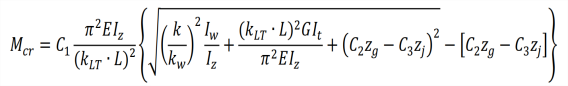
With:
Haunched sections (I+Ivar, Iw+Plvar, Iw+Iwvar, Iw+Ivar, I+Iwvar) and composed rail sections (Iw+rail, Iwn+rail, I+rail, I+2PL+rail, I+PL+rail, I+2L+rail, I+Ud+rail) are considered as equivalent asymmetric I sections.
For advanced Lateral Torsional buckling analysis, see "Annex D: Use of sheeting ".