Defining a new grid pinned connection
The procedure for the definition of a new grid pinned connection will be shown on an example of a horizontal beam attached to the second horizontal beam in the middle of its length. However, other configurations are possible as well.
The procedure to define a new grid pinned connection
Let’s have two intersecting (joining) horizontal beams.

Open service Steel. Start function Connections > Grid pinned. Follow the instructions on the command line and select the point of connection.

All the beams that pass the selected node are selected. If required, unselect unnecessary beams.

Press [Esc] to complete the action. The connection is generated in the selected node and a connection symbol is drawn on the screen.

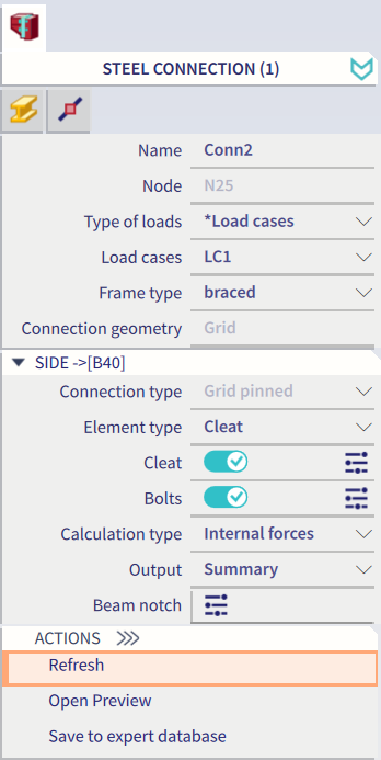
Use the property window to define all required parts of the new connection.
The connection in the graphical window is redrawn to reflect your settings.

Note: Remember that a linked node must exist in the selected node where connection is to be defined.
Note: The beam that passes the connection must have HIGHER priority than the beam that ends in the connection. E.g. like below:

The priority can be adjusted in the property dialogue of each beam in the field Type or in group CAD model:

