Joint Configuration
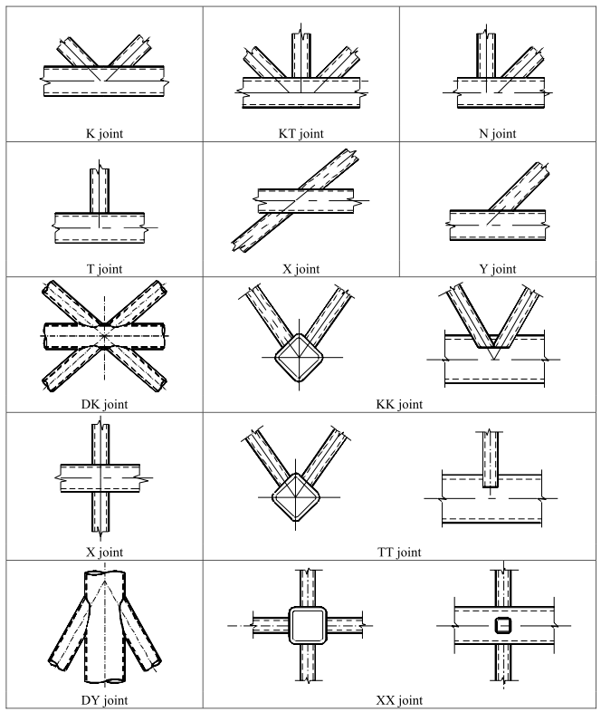
The design procedure defined by the EN 1993-1-8 Article 7, may be applied to joint types specified in EN 1993-1-8 Article 7.1.2 Table 7.1. In SCIA Engineer uniplanar configurations T, Y, X, N, K, DY and DK are currently supported.
Automatic recognition
The automatic recognition of joint configuration is based on the Structural model, taking into account all members selected during input of the joint object. The recognition is processed in several steps:
- List of all selected members is created.
- Members with the highest value of Structure type are marked as chord members. User may use for example type truss chord with value of 95.
- Remaining members are marked as brace members. User may use for example type truss diagonal with value of 90.
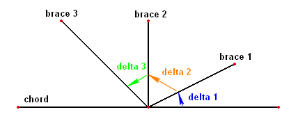
- For each brace member respective delta angle between the brace member and the chord member is measured .
- The brace member with the smallest delta angle is marked as brace 1.
- Depending on the number of brace members, an additional delta angles between brace members are measured. The angles are measured in a continuous direction from angle delta 1. See example picture below.
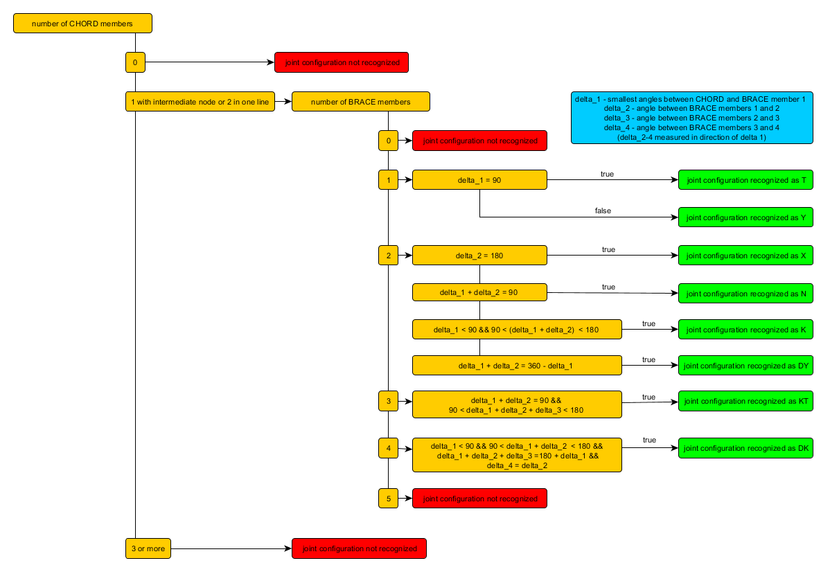
- The algorithm indicated on the picture below is used for the final determination of the joint configuration.
An additional per-plane validation tests need to be fulfilled in the structural model:
- Axes of all members has to be in one plane.
- Chord members has to be in line, which in terms means use the same eccentricity.
- For T, Y, X, DY and DK joint configurations, all the members need to have one intersection point.
An additional cross-section validation tests need to be fulfilled:
-
Only circular Hollow Section joints are supported. They also have to be marked by SCIA Engineer as a formcode 3 cross section
- The cross-section id of the chord members have to be identical.
An additional geometry validation tests need to be fulfilled in the structural model:
- Continuous chord members are supported.
- Continuous brace members are not supported.
- The curved members are not supported.
If the configuration is not recognized, an error massage is displayed during the input of the joint object. User may also modify the geometry or member attributes when a joint already exists and in such case recognized joint configuration is changed to "Not Recognized".
The brace member index used for the recognition may not be in line with brace member index used in the resistance calculation. There the numbering of the braces is based on the actual design internal forces .
Gap / Overlap
Geometric definition of gap and overlap is given by EN 1993-1-8 Article 1.5 Figure 1.3. Within SCIA Engineer the Gap / Overlap definition parameters are only valid and displayed for N, K and DK joint configurations.
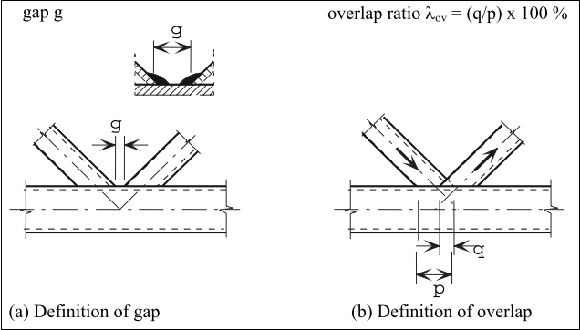
Integer subscripts for overlapped and overlapping brace members are given by EN 1993-1-8 Article 1.5 (4). Overlapped brace member is denoted by index j and overlapping brace member is denoted by index i.
Either gap or overlap is calculated automatically by default using the structural model geometry and the value is shown in the properties of the joint object with reference to identified brace members. The formulas for calculation of gap, overlap and also eccentricity are based on a CIDECT publication "Design guide for circular hollow section (CHS) joints under predominantly static loading", 2008:

Note that a negative value of the gap g in the equation above corresponds to an overlap q.

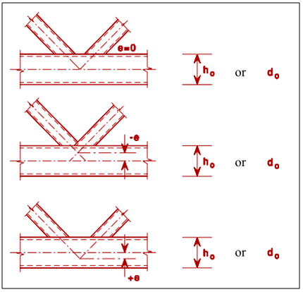
Eccentricity of joint is defined by EN 1993-1-8 Article 5.1.5 Figure 5.3.
User is also allowed to input direct values of gap or overlap or define it through manual input of eccentricity. This may be done through "Definition" combo-box item in the properties where the user may select from several options:
- From structural model - Default option. Both gap and overlap is calculated automatically using the structural model geometry. Eccentricity, gap or overlap items are disabled for editing.
- Eccentricity - Direct input of eccentricity. Gap or overlap is calculated based on the defined eccentricity value and is disabled for editing. Valid input range is <-1;1>[m].
- Gap - Direct input of gap. Eccentricity is calculated based on the defined gap value and is disabled for editing. Valid input range is <0;1>[m].
- Overlap - Direct input of overlap. Eccentricity is calculated based on the defined overlap value and is disabled for editing. Valid input range is <0;110>[%].
User definition of gap and overlap in a joint is kept after change of joint member cross-sections.
In case of overlap the overlapping brace is also shown in the properties.
Automatic recognition of the overlapping brace:
- In the case of different structural types of brace members, the overlapping is based on the structural type values. The brace member with lower value will be overlapping.
- In case the structural type is the same for both brace members - the overlapping is based on conditions given by EN 1993-1-8 Article 7.1.2 (7-8). In case the conditions acts against each other, the overlapping brace is based on (8).