Resistance
Connection geometry and design bending moment may be seen on the picture below:
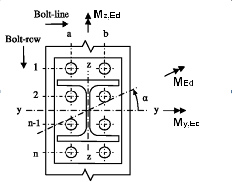
The strong-axis moment resistance Mj,y,Rd of the joint is determined based on EN 1993-1-8, assuming no weak-axis bending influence. Similarly to this, it is assumed that the strong-axis moment bending will not influence calculation of weak-axis moment resistance Mj,z,Rd of the joint.
The weak-axis moment resistance Mj,z,Rd of the joint may be determined by:

with:
| y | is the design distance from the bolt-line in tension to the center of compression for weak-axis bending. The leverage arm is dependent on the stiffness of the components. Within SCIA Engineer it is assumed, that joint components are infinitely stiff. The additional split is based on the type of the bolts |
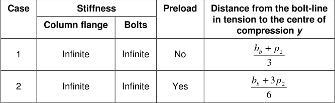
with:
| bb | is the width of the beam (in case of non-symmetric beam or splice connection the minimum is used |
| p2 | is the horizontal spacing between the two lines of bolts |
Fta,Rd-is the effective design tension resistance of a bolt-line for the weak-axis moment calculation taken as:

with:
| Fta,fc,Rd | is the design tension resistance for bolt-line a of the column flange in transverse bending |
| Fta,ep,Rd | is the design tension resistance for bolt-line a of the end-plate in bending |
| Fcb,fb,Rd | is the design compression resistance for bolt-line b of the beam flange in compression |
| Fta,fct,Rd | is the design tension resistance for bolt-line a of the column flange in twisting |
| Fta,wbc,Rd | is the design tension resistance for bolt-line a of the column web in bending |
For splice connections only Fta,ep,Rd and Fcb,fb,Rd component resistances are calculated for each side and minimum resistance from the four components is taken as Fta,Rd.
Calculation of the weak-axis components may be seen below:
Column flange in bending
The component resistance Fta,fc,Rd for each bolt-row is already calculated according to EN 1993-1-8 Art.6.2.6.4 in strong-axis moment resistance calculation as resistance Ft,fc,Rd. The final bolt-row resistances for that component are shown in the appropriate columns in the table of potential tension resistances, where the individual and group approaches are accounted for.
Since tension of weak-axis bending concerns only one side of the connected member, the final weak-axis component resistance for each bolt Fta,fc,Rd is calculated as Ft,fc,Rd, divided by two.
For further info on the calculation of the strong-axis Ft,fc,Rd component resistance see chapter: "Column flange in transverse bending".
End plate in bending
The component resistance Fta,ep,Rd for each bolt-row is already calculated according to EN 1993-1-8 Art.6.2.6.5 in strong-axis moment resistance calculation as resistance Ft,ep,Rd. The final bolt-row resistances for that component are shown in the appropriate columns in the table of potential tension resistances, where the individual and group approaches are accounted for.
Since tension of weak-axis bending concerns only one side of the connected member, the final weak-axis component resistance for each bolt Fta,ep,Rd is calculated as Ft,ep,Rd, divided by two.
Minor modification in calculation of effective length for individual approach is done for bolt-rows classified as "Bolt-row outside of beam". Compared to the strong-axis calculation, the patterns breaching the z-axis of the connected beam were removed. Weak-axis calculation formulas for the given classification may be seen below:
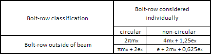
The T-stub resistance of such bolt-row is calculated in a standard way, only using modified effective length. The re-calculated weak-axis component resistance is used with full value in the Fta,ep,Rd resistance.
For further info on the calculation of the strong-axis Ft,ep,Rd component resistance see chapter: "End-plate in bending".
Beam flange in compression
The design component resistance Fcb.fb.Rd may be taken as the design compression resistance of one beam flange. Final resistance of the component is given as:
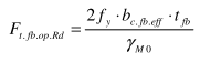
with:
| fy | is the yield strength of the beam |
| tfb | is the thickness of the beam flange |
| γM0 | is the partial safety factor for resistance of cross-sections |
| beff,wbc | is the effective width of the component given as: |
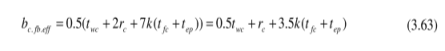
but not greater than :
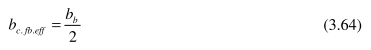
For splice connection the bc,fb,eff is calculated only as:
where:
| twc | is the thickness of the column web |
| tfc | is the thickness of the column flange |
| tep | is the thickness of the end-plate |
| rc | is the rounding r1 of the column |
| bb | is the width of the beam |
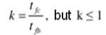
| k | thickness reduction coefficient given as: |
In case of non-symmetric beam is used, calculation is assuming symmetric section while using the minimum value.
Column flange in twisting
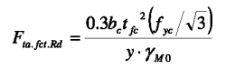
The design resistance of the bolt-line in tension for the column flange in twisting Fta,fct,Rd is taken as :
with:
| bc | is the width of the column |
| tfc | is the thickness of the column flange |
| fyc | is the yield strength of the column |
| γM0 | is the partial safety factor for resistance of cross-sections |
| y | is the design distance from the bolt-line in tension to the center of compression for weak-axis bending |
Column web in bending
For determination of the design resistance of the bolt -line in tension for the column web in bending Fta,wbc,Rd the effective length of the web in bending beff,wbc is proposed to be calculated assuming a maximum spread at 60° from the outer bolts.
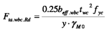
with:
| twc | is the web thickness of the column web |
| beff,wbc | is the effective length of the web in bending given as: |
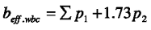
with:
| ∑p1 | is the vertical spacing between the first and last bolt-row |
| p2 | is the horizontal spacing between the two bolt-lines |