Automatic Mesh Refinement (AMR) - since SCIA Engineer v 24.0
Introduction
This chapter is to provide a closer information about newly introduced Automatic Mesh Refinement (AMR) process, which was reintroduced (and improved in order to be more automatic) since SCIA Engineer version 24.0. The AMR process is automatic refinement of the finite element mesh on 2D members.
How to use AMR
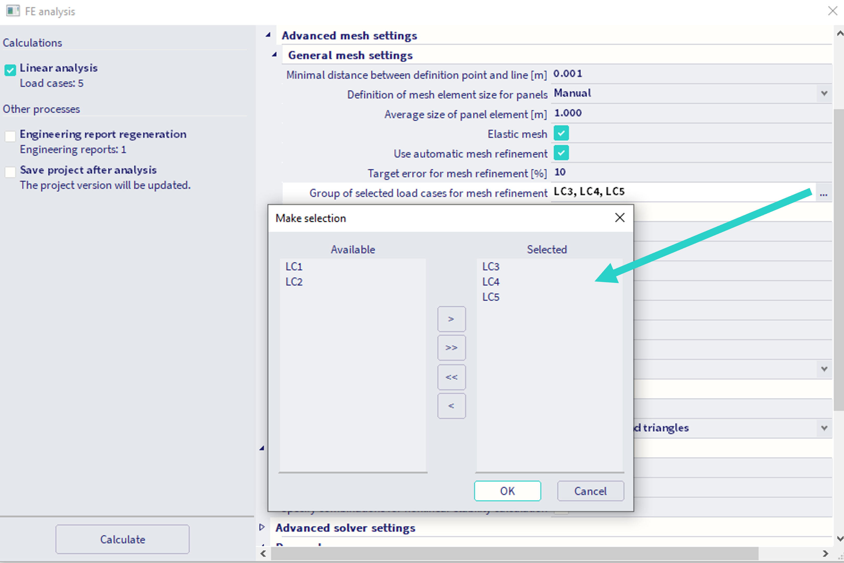
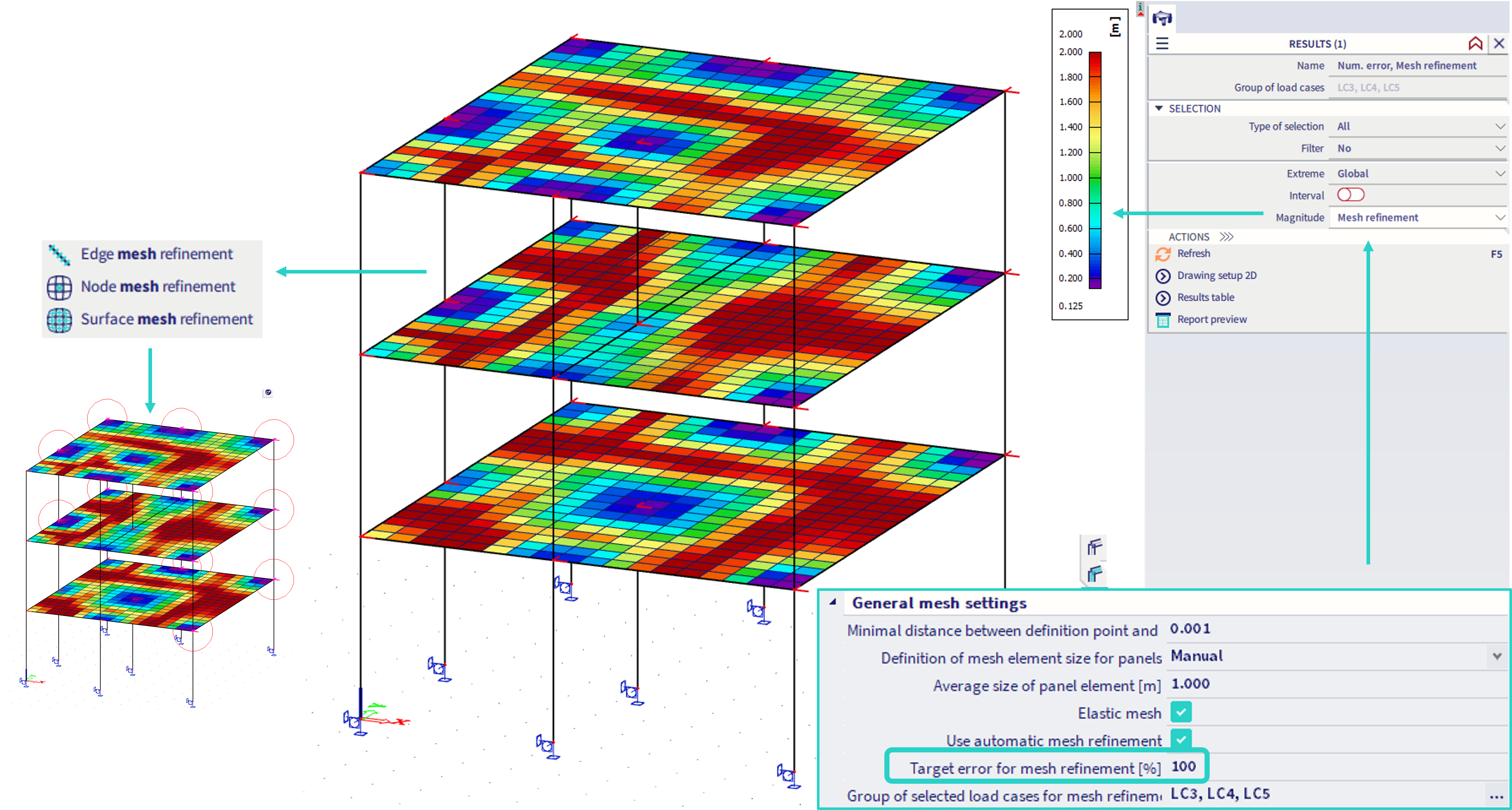
In order to use the automatic mesh refinement process, the property "Elastic mesh" within the "General mesh settings" needs to be activated. Upon activation, the property "Use automatic mesh refinement" appears within these settings. When this setting is activated, another two settings appear:
Target error for mesh refinement [%] - default value is 10 - this value determines the objective for the iterative process running in the background. User might influence the mesh refinement through this value: the larger this target error, the coarser the mesh after the automatic refinement will be. Smaller target error values result in the finer meshes. The value denotes the maximum (through all the 2D members present in the project) of so called "total relative energetic error" of the "MEER" algorithm (see the references)
Group of selected load cases for mesh refinement - The mesh is being refined with respect of certain applied loads. The user needs to select load cases (linear load cases are available for the selection), from which this load will be considered. The algorithm runs once - considering linear superposition of all the loads contained in these load cases (linear combination of these load cases, each with multiplication of 1.0 is considered in the background).
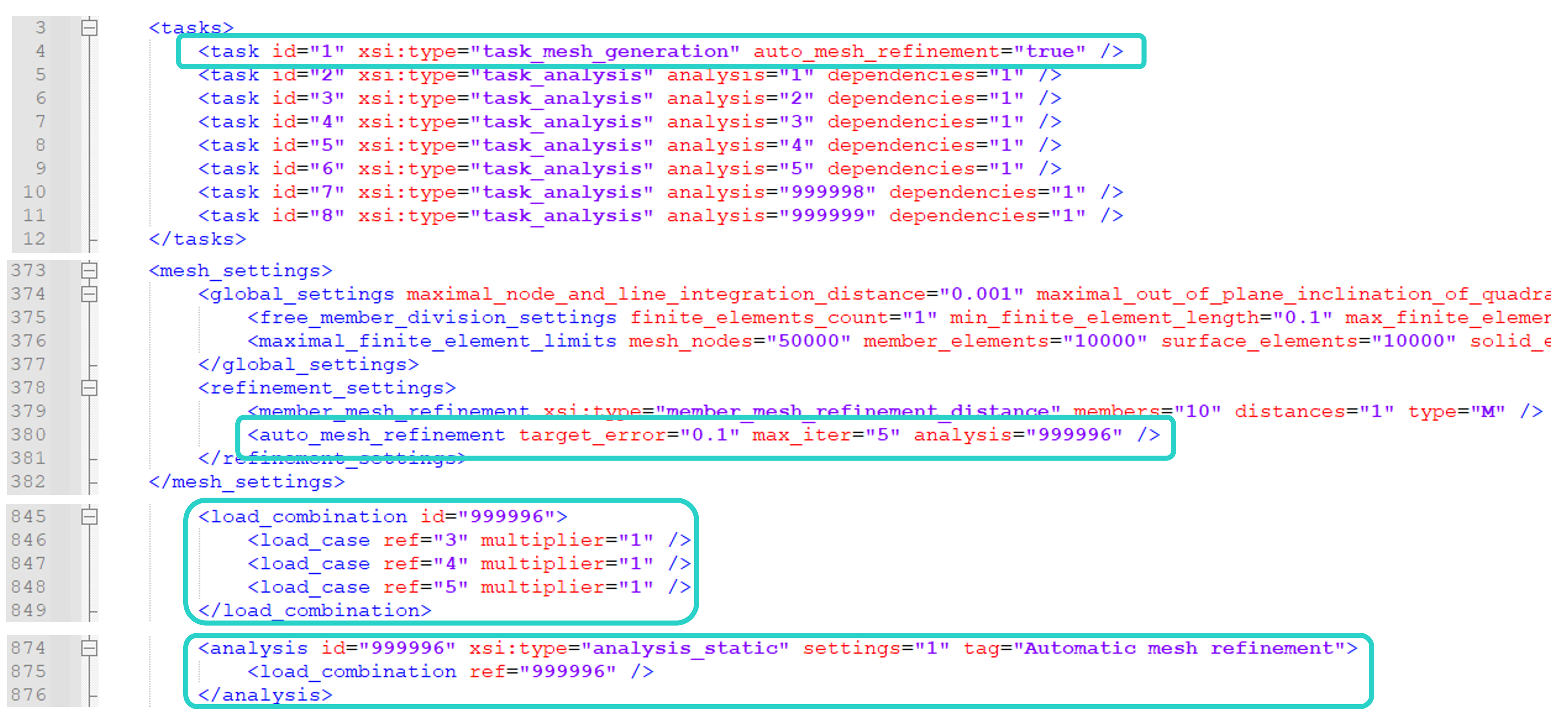
The internal call of the AMR is depicted in the figure below (this is content of the XML file from TEMP folder, which will be sent to FEM solver). Internally the linear combination of these load is numbered as 999996. Also, the export contains entity "max_iter=5". Internally the AMR is iterative process, where the mesh is refined in order to achieve the specified objective (the target error). As the AMR algorithm tends to refine the mesh near the singularities (nodal supports, etc.), the process is limited to maximal number of iterations, in order to avoid too fine mesh with too small mesh elements. This setting of maximum of 5 iterations is internal, not possible to be changed in the GUI by the user. Nevertheless, values larger then 5 are not recommended.
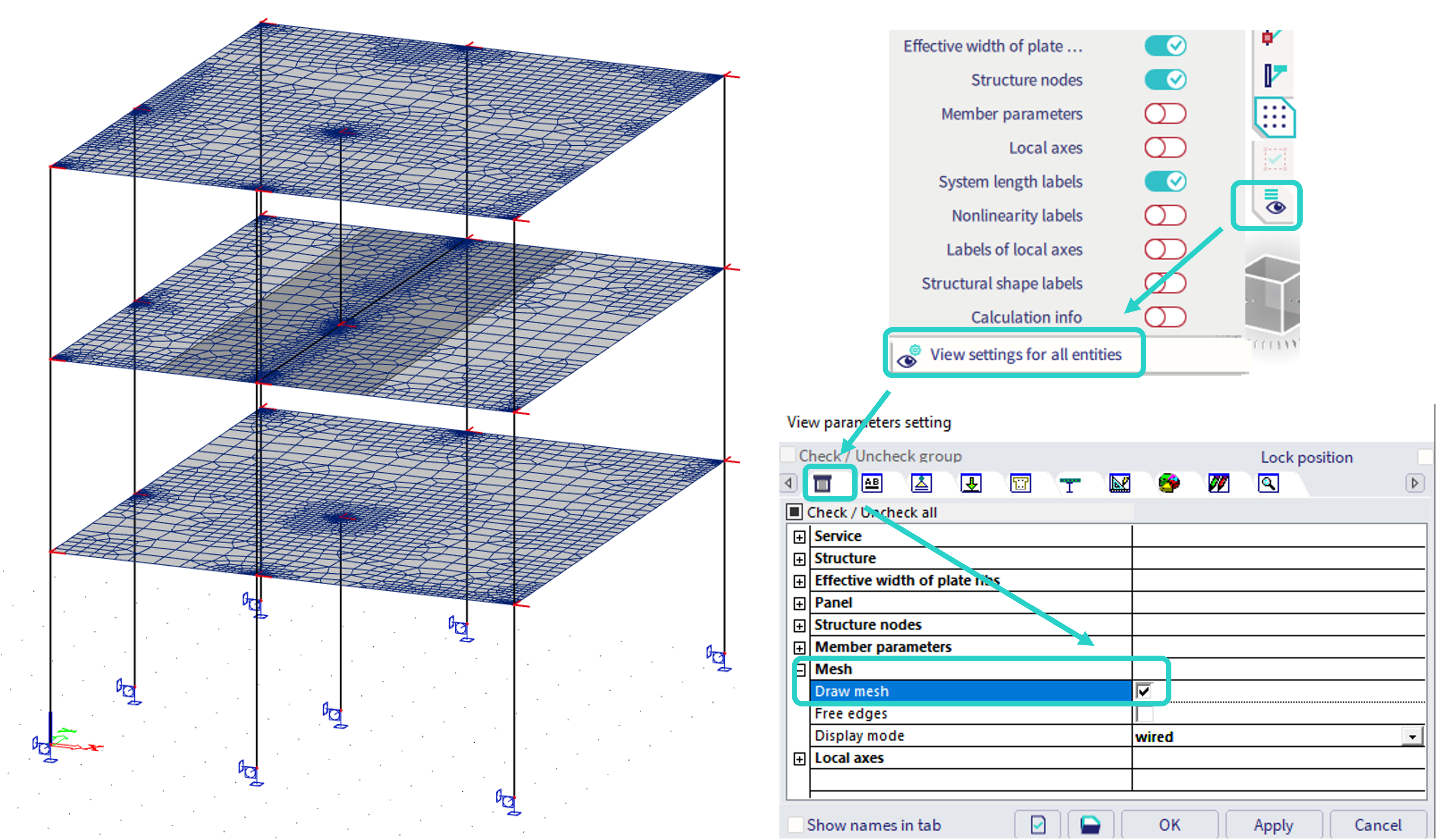
After the AMR process, the user is recommended to check the refined mesh, whether this is not too fine (by the user's own judgement). To see the mesh, turn on the option "draw mesh" within the "view parameters settings":
AMR numerical results
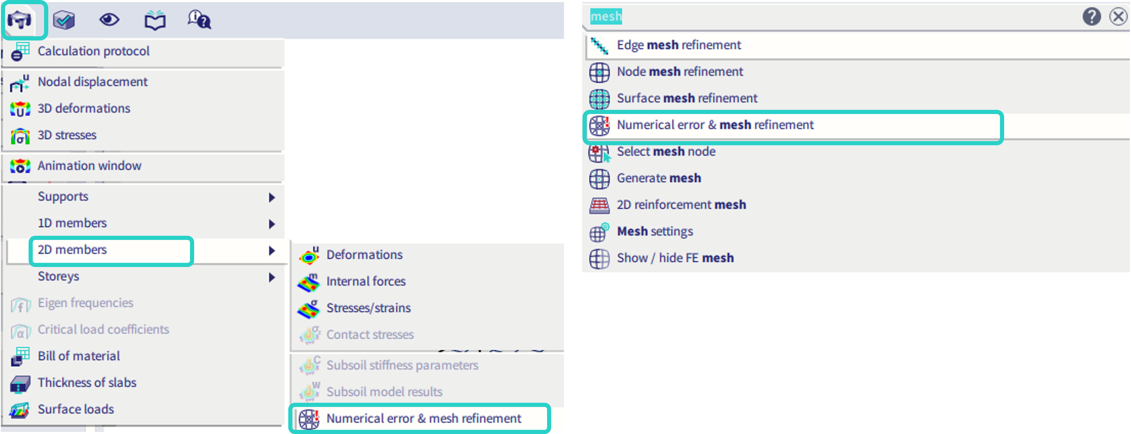
The process of the AMR uses certain internal variables during the iterative refinement process. The values of two of these variables after the final iteration (maximum the fifth iteration) are available to be checked by the user in GUI within the result service "Numerical error and mesh refinement". This service might be approached through SCIA Spotlight by typing the keyword "mesh" and selecting the corresponding service, or in the "results" - "2D members". This result service is not included in the "process tool bar" by default, as the use of this results is not expected to be so frequent by the user.
Mesh refinement (result) - in units of length
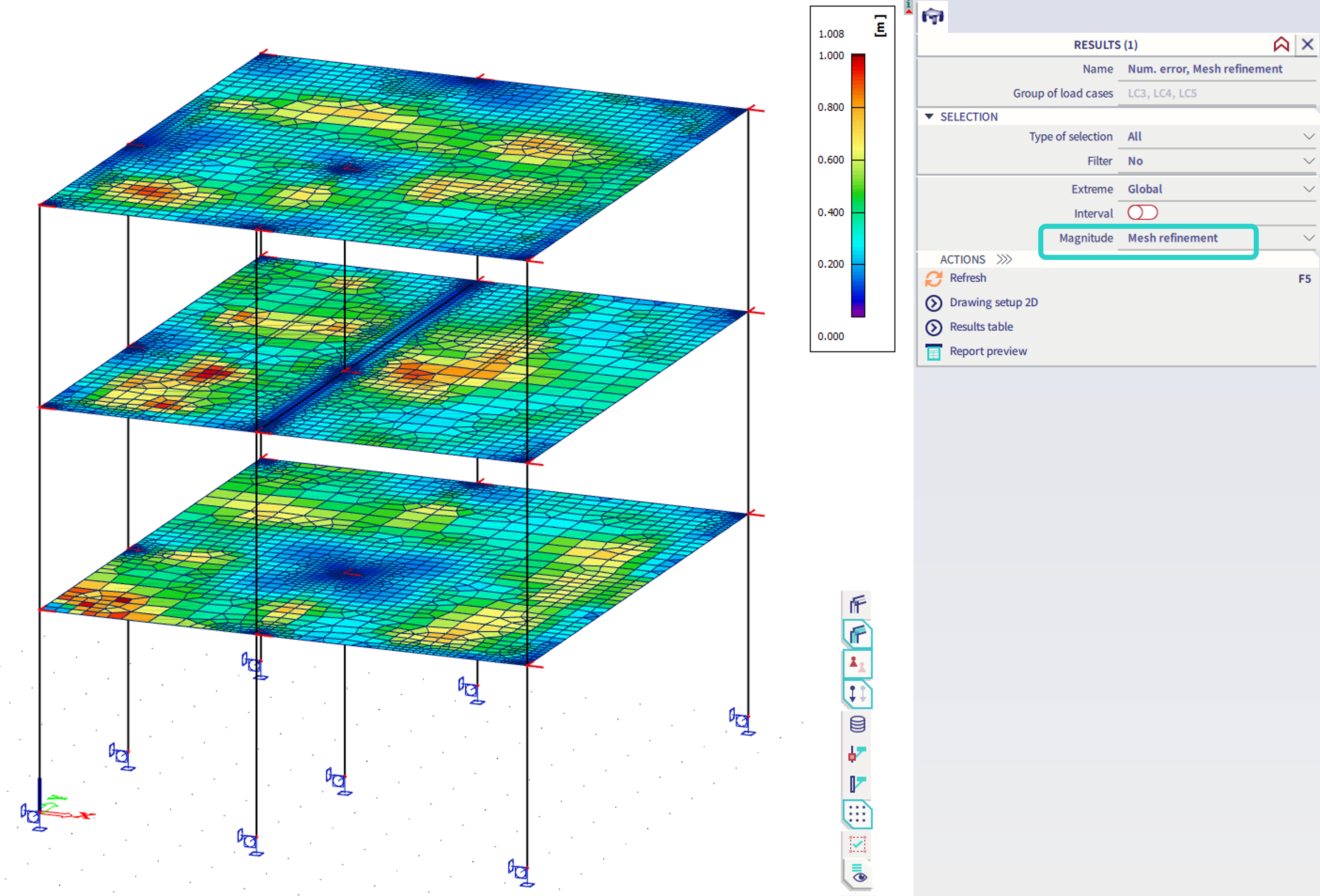
This result of 2D members provides information of the mesh size (edge width) of the 2D finite elements for the subsequent iteration of the AMR process. This result does not provide the actual size of the 2D finite elements. This result was kept there, as it was available in the older version of mesh refinement, which was not automatic, and user needed to run each iteration manually. In the current implementation (since v 24.0), the process is automatic, and maximum 5 iterations are performed. It is possible this result might be used in several ways:
- to check the 2D mesh size just approximately - the size of the mesh is usually close (at least by magnitude order) to what is displayed by this result (the size for next possible AMR iteration)
- to see in which areas the refinement is not needed (in accordance with MEER assumptions) - the result determines the areas, where coarser mesh is sufficient (but was possible refined due to refinement of the neighbouring 2D elements, in order to get more uniformly refined mesh)
- to use it as a recommendation for manual mesh refinement (as shown in the figure below). Hence, in the first step, the large target error is set (e.g. 100 or 1000%), so that during the AMR process, there is only one iteration, where nothing is refined (due to large target error). Nevertheless, the algorithm provides results for the second iteration, where the areas recommended to be refined are shown graphically (areas with smaller values of the result). Note that the result value does not specify the exact recommended size of the 2D mesh elements in these areas. The areas recommended for refinement are usually near singularity points, or locations of larger loads. The user might then manually input selected mesh refinement entities, e.g. the "node mesh refinement", as shown in the figure below (if the user does not like the shape of the automatically refined mesh):
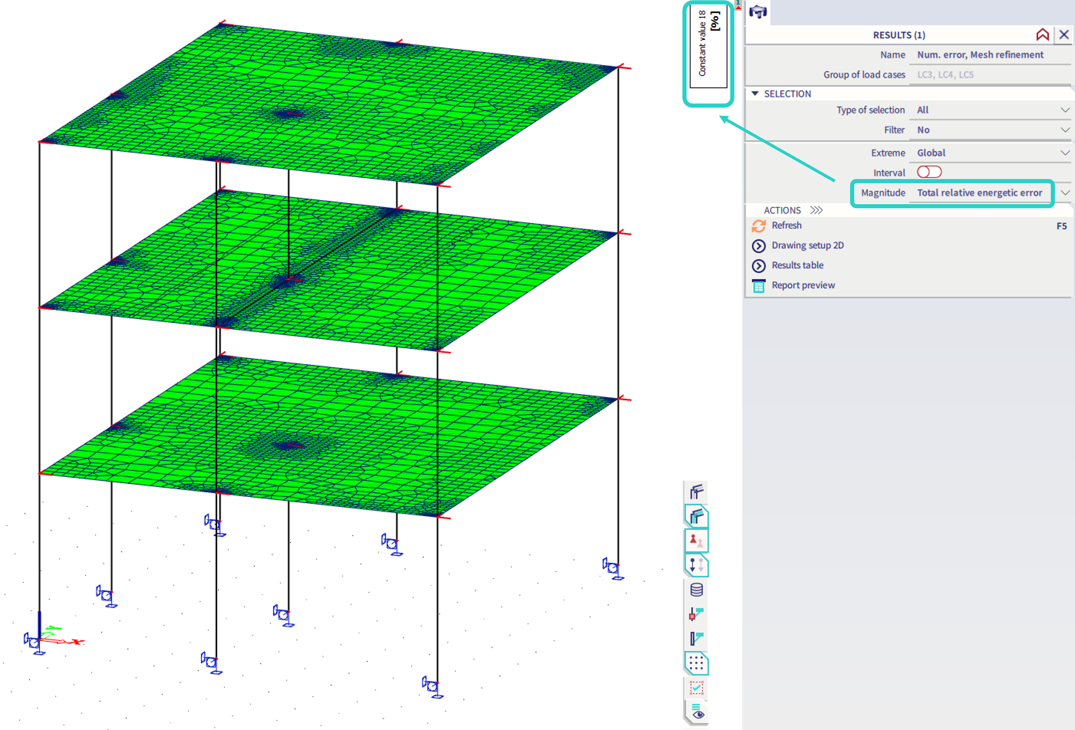
Total relative energetic error (result) - in %
This is the converged value of the objective (the target error for mesh element) defined by the user as the input parameter for the AMR process. The result depicts the maximal value from all the 2D elements, which is graphically plotted uniformly on all the 2D members, but practical meaning is sufficiently expressed by the constant value in the upper-right corner. Note that the depiction of this value is rather informative, in order to see what maximal input value of the target error is just enough to make AMR process to converge to the current refined mesh shape. This value does not provide the error value of the numerical solution itself (hence, if this value is e.g. 50, it does not mean the results are 50% off).
Examples
In case there is no limitation for the minimal mesh element within the project, larger values of the Target error for mesh refinement are recommended.
Silo structure
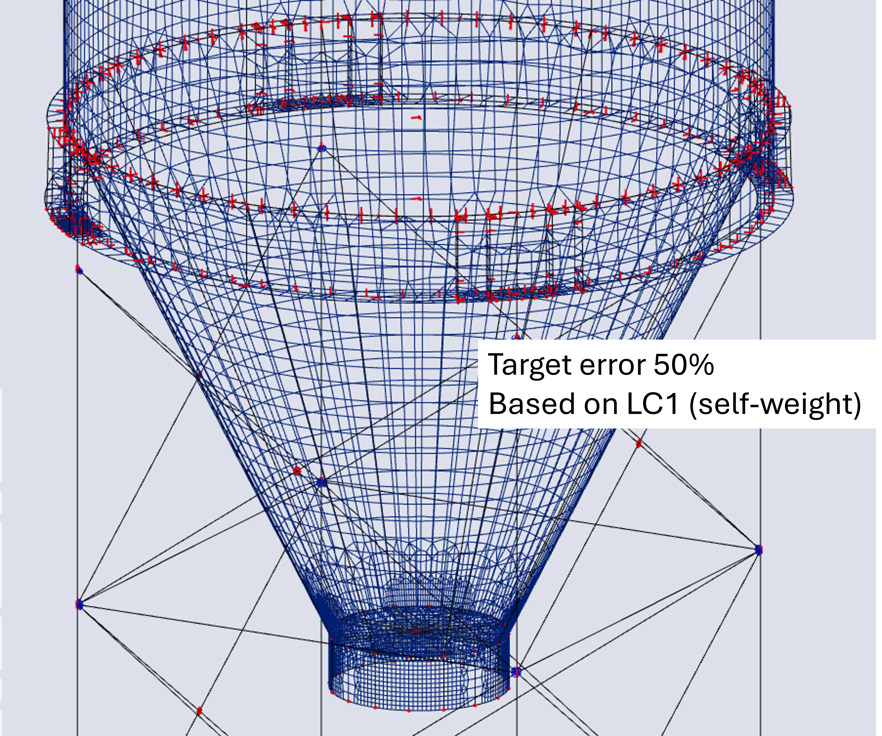
If the minimal size of the mesh element is not limited, it has been observed, the Target error for mesh refinement is suitable to be set for 50%.
In the figure below, there is example of too fine mesh with setting: target error for mesh refinement = 20%.
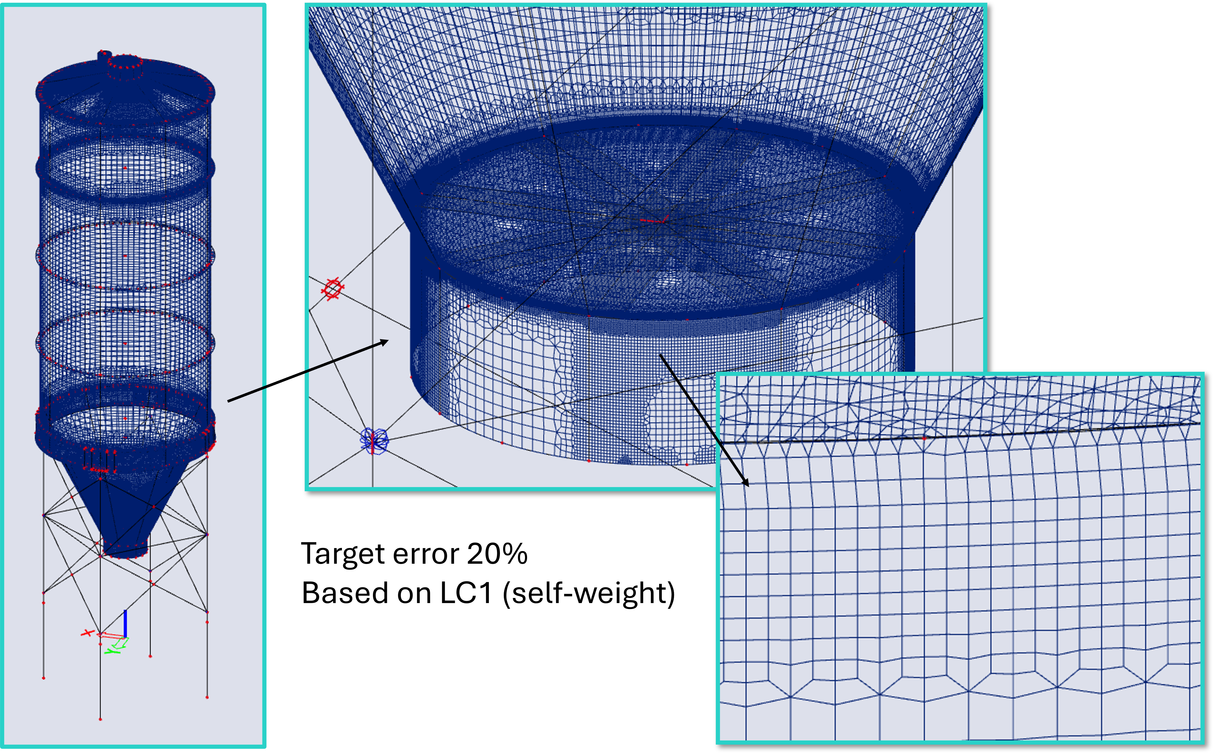
If the value is set to 50%, the mesh is refined but not too much, hence appears more suitable:
MEER algorithm for AMR
The process of the AMR utilizes the Modul for Error Estimation and Refinement (MEER), and some information are available in Czech language, as this module was developed in cooperation with ČVUT - Czech University of Technology:
MEER Documentation (in Czech language)
MEER 0.1 (in Czech language)
The MEER modul was created as part of the TAČR project TA02011196 (in English language) in years 2012 - 2015.