Phased cross-section
This chapter is related to the Analysis of construction stages
Modules Construction stages
Phased cross-sections can be created as a General cross-section. General cross-section can be defined by means of a polygon drawing or by conversion from other types of database cross-sections. Also some pre-defined bridge cross-sections can be defined as phased. Up to ten phases can be defined for one cross-section.
Detailed information on general cross-section module is given in chapter Cross-sections > General cross-section. The important limitation in SCIA Engineer is that only one phased cross-section can be defined for one 1D member! Therefore it is not possible to use the phased cross-section in the arbitrary beam (i.e. the 1D member consisting of several sections made of different cross-sections).
One important condition must be fulfilled when a phased general cross-section is created. The condition is clear from the following picture.

Example of a phased cross-section
The following picture shows a hollow core floor slab [phase 1] (400 mm high) with a 50 mm topping [phase 2].

Mesh size for beams with phased cross-section
A beam with phased cross-section requires rather fine (finite element) mesh. This fine mesh is necessary to produce good and reliable results.
The size of finite elements for beams with a phased cross-section is determined by parameter Average size of cables, tendons, elements on subsoil from the FE Mesh Setup Dialogue.
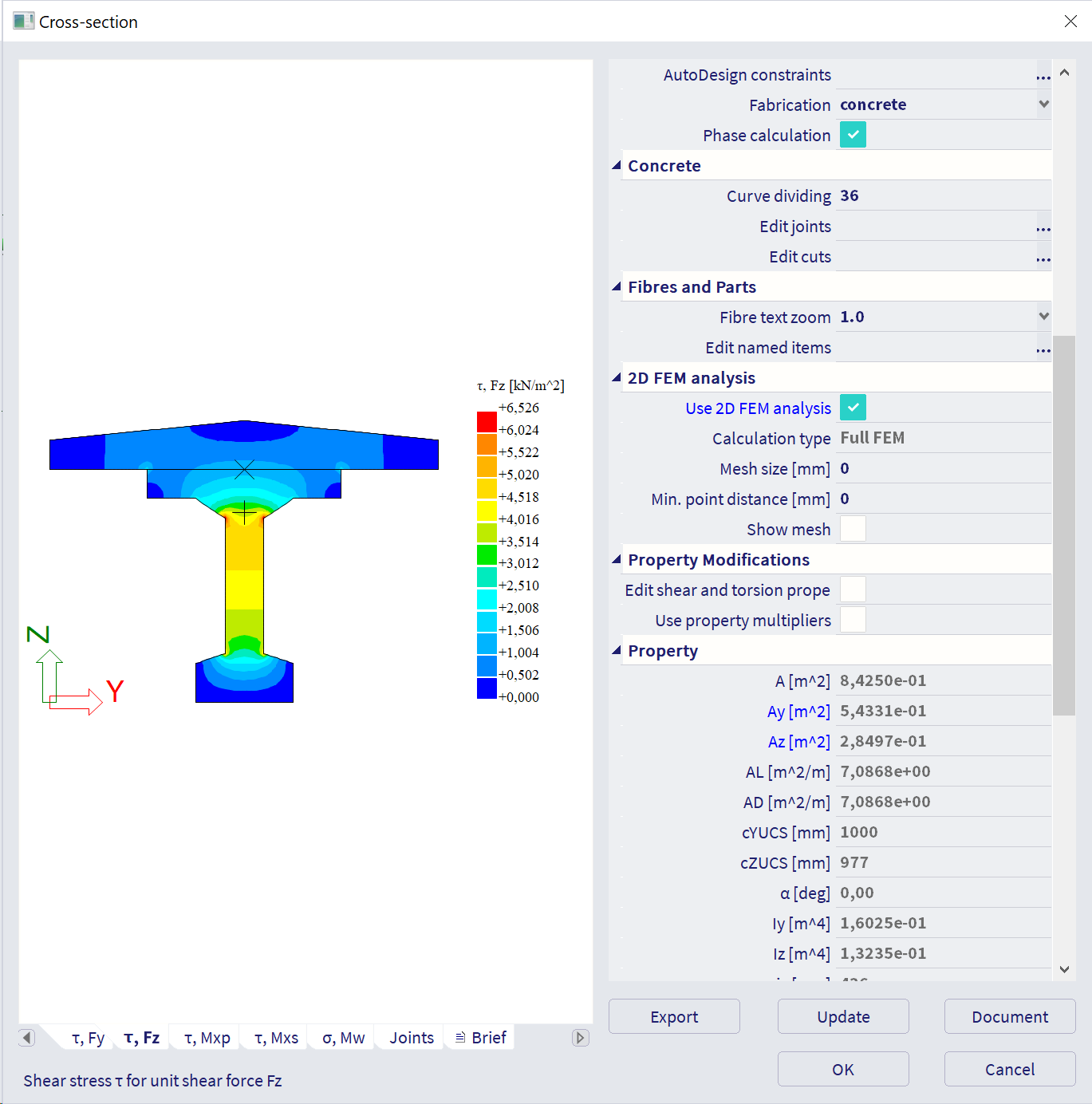
Sectional characteristics of phased cross-section
It is automatically set to use Full FEM method analysis for the calculation of sectional characteristics of a phased cross-section. This can be done in the editing dialogue of a cross-section by ticking (selecting) the option Full FEM. When this option is ON, the program starts a special engine to calculate the sectional characteristics.
The result of the analysis is shown in a separate dialogue.
Grashoff-Jouravski method is disabled for phased CSS. If you open old example where this method was set then its automatically switched to Full Fem method during opening of esa file with a message.

As you can see from the message above also the fibres of phased CSS are also recalculated to generate fibres in principal centroid axis corresponding to of particular state of phased CSS.
| Phased cross-section | Fibre before version 24.0 | Fibre from version 24.0 |

|

|

|
It is possible to view some results and also to select the way for the determination of shear-related parameters: Ay/A and Az/A (see the note below).
Note: It is up to the user to review the shear-related values and select the correct (or most correct) one manually.
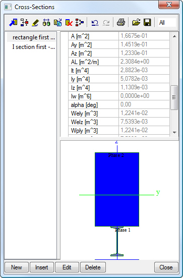
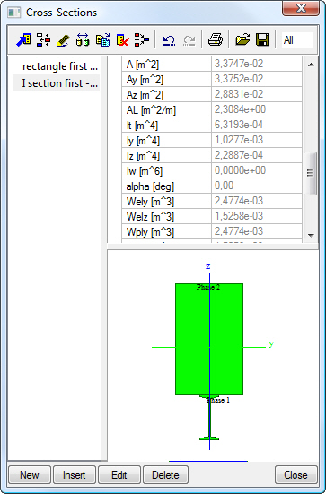
Sectional characteristics for multi-material sections
The sectional characteristics are transformed to an ideal sectional characteristics.
For phased cross-sections from the program library, the characteristics are related to the material of the first phase of the cross-section (i.e. the material of the part of the cross-section that forms the first phase).
For general cross-sections, the characteristics are related to the material of the first input part of the cross-section independently on phases.
Compare the two images below. The same general cross-section consisting of a concrete rectangular section and steel I section. In the first one, the rectangle was defined as the first part. In the second one, the I-section was defined as the first part.
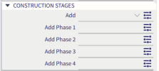
Defining the introduction of a new phase of the cross-section
This chapter deals with the introduction of a new part of a phased cross-section, e.g. casting of composite slab, etc.
Procedure to install a new cross-section phase
-
Select the 1D member with the phased cross-section.
-
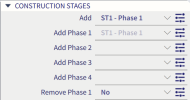
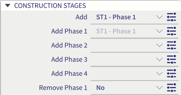
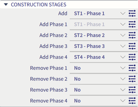
The property window displays the dynamic properties of the all cross-section phases with no stage assignment.
-
Item Add and Add phase 1 is automatically pre-filled when you use function Add member and select 1D member with phased cross-section.
-
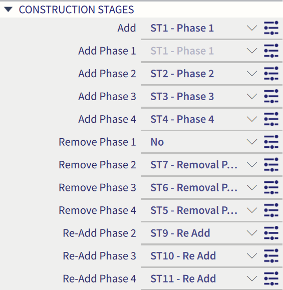
Then you can add construction stages for adding other cross-section phases
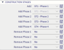
-
As you can see there are also automatically offered stages for removal of particular cross-section phases. This can be used for some temporary parts of cross-section or for retrofitting. Finally you can Re-Add already removed cross-section part.
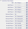
Maximally one Remove and one Re-Add is available for each cross-section phase.
Self-weight load on phased cross-section
Self-weight of phased cross-section can be respected in the several ways:
- use LC type permanent - self-weight
- use LC type permanent - standard and recalculation the load of the new part by hand and define standard line load
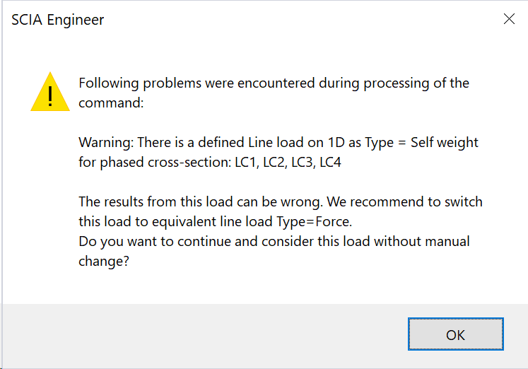
- use LC type permanent - standard and define line load by special lien load - self-weight

If the third option is used for phased cross-section then new message appears during the calculation. So we recommend to use option 1 or 2 for phased cross-section
Conversion of old files
It was necessary to guarantee also the conversion of old *.esa files especially from the point of phases removals due to different behaviour in old and new version.
In case of old example has
- Remove NO -> then in new version all phases components will be set as NO for removal parts
- Remove YES -> then in new version all phases components will be set as YES for removal parts