P-delta effects in seismic analysis
Introduction
In case second-order effects (P-delta) need to be taken into account in a seismic analysis, it can/should be done at a certain level in SCIA Engineer.
P-delta effects affect the dynamic behaviour
Compression in supporting members (columns, walls) amplifies the sway of the structure. Natural periods and lateral displacements tend to increase.
That can be considered in the analysis by adding a so-called geometric stiffness component in the stiffness matrix of supporting members, causing them to appear softer.
It is, by the way, the same geometric stiffness component that causes cables to appear transversally stiffer when under tension. Members under tension appear transversally stiffer, members under compression appear transversally softer, due to second-order effects.
Seismic load cases computed via spectral analysis use a modal superposition of mode shapes, which, consequently, will include P-delta effects as well.
Please note a fundamental assumption of 2nd order theory: P-delta effects are based on a predefined axial stress state in members. Therefore, the analysis is valid as long as compression forces in supporting members is not modified significantly by transversal loading.
In SCIA Engineer
You can consider P-delta effects in a seismic analysis in SCIA Engineer via the use of initial stresses - this approach allows to consider P-delta effects in the modal analysis and their effect on natural periods and mode shapes, using the stress state obtained from a single load case. That approach is supported in all versions of SCIA Engineer.
P-delta effects using initial stresses
This approach is supported in all versions of SCIA Engineer. It requires no additional license than what is needed for standard seismic analysis.
This approach requires that a load case is defined, that reproduces the desired initial state - i.e. quasi-permanent state - for the seismic analysis.
It also implies, that only the modal seismic spectral analysis will be carried out with P-delta effects. The quasi-permanent state will be computed linearly.
1 Project settings
Only regular project settings for seismic analysis are needed. Initial stress functionality is enabled by default.

2 Initial stress input
Create a load case that contains all permanent and quasi-permanent loads.
In the example below:
- surface loads on all slabs:
- self-weight = 0.2 * 2.5 * 9.81 = 4.905 kN/m2
- dead load = 3 kN/m2
- quasi-permanent part of live load = 0.3 * 2 = 0.6 kN/m2
- total = 8.505 kN/m2
- self-weight line loads on all columns

3 Solver settings
In solver settings, enable initial stress and select the correct load case for initial stress state.

4 Combine static & seismic results
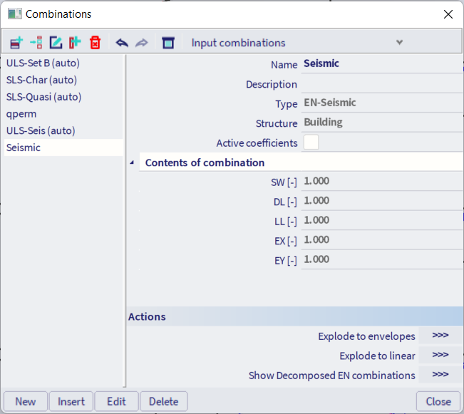
The seismic load case combination is defined exactly in the same way as for a normal linear analysis.
Create a linear seismic combination containing
- the static load cases included in the quasi-permanent state
- the seismic load cases
Results
Comparing results from 3 approaches:
- linear analysis - without P-delta effects
- initial stress - with P-delta effects in modal and seismic spectral analysis
Modal analysis
| Period | ||
| Mode | without P-delta | initial stress |

|

|
|
| 1 | 2.47 s | 2.93 s |
| 2 | 1.94 s | 2.10 s |
| 3 | 1.65 s | 1.80 s |
| 4 | 0.63 s | 0.66 s |
Displacements under seismic loading
| Displacement | ||
| Storey | without P-delta | initial stress |

|

|
|
| 3 | 11.5 mm | 13.3 mm |
| 2 | 9.5 mm | 11.2 mm |
| 1 | 6.1 mm | 7.3 mm |
Total shear force per storey
| Shear force | ||
| Storey | without P-delta | initial stress |

|

|
|
| 3 | 15.41 kN | 15.30 kN |
| 2 | 28.35 kN | 28.30 kN |
| 1 | 36.61 kN | 36.73 kN |
Bending moment in a column under seismic load case alone
| Max moment in column | ||
| Storey | without P-delta | initial stress |

|

|
|
| 3 | 9.95 kNm | 10.75 kNm |
| 2 | 16.26 kNm | 18.58 kNm |
| 1 | 22.40 kNm | 26.51 kNm |
Bending moment in a column under seismic combination
Note: here, the values in the column 'initial stress' do not include second-order effects for the static load cases.
| Max moment in column | ||
| Storey | without P-delta | initial stress |

|

|
|
| 3 | 67.97 kNm | 68.77 kNm |
| 2 | 53.52 kNm | 55.84 kNm |
| 1 | 49.80 kNm | 53.92 kNm |