Stud Design
The program will determine the number of studs and the layout of the studs along a member when the calculation approach is set to 'Design'. When set to 'Check' the number of studs is simply input in the setup or member data (as stud spacing or trough spacing) and the stud layout diagram will simply reflect this input. The information that follows is relevant only for the 'Design' approach.
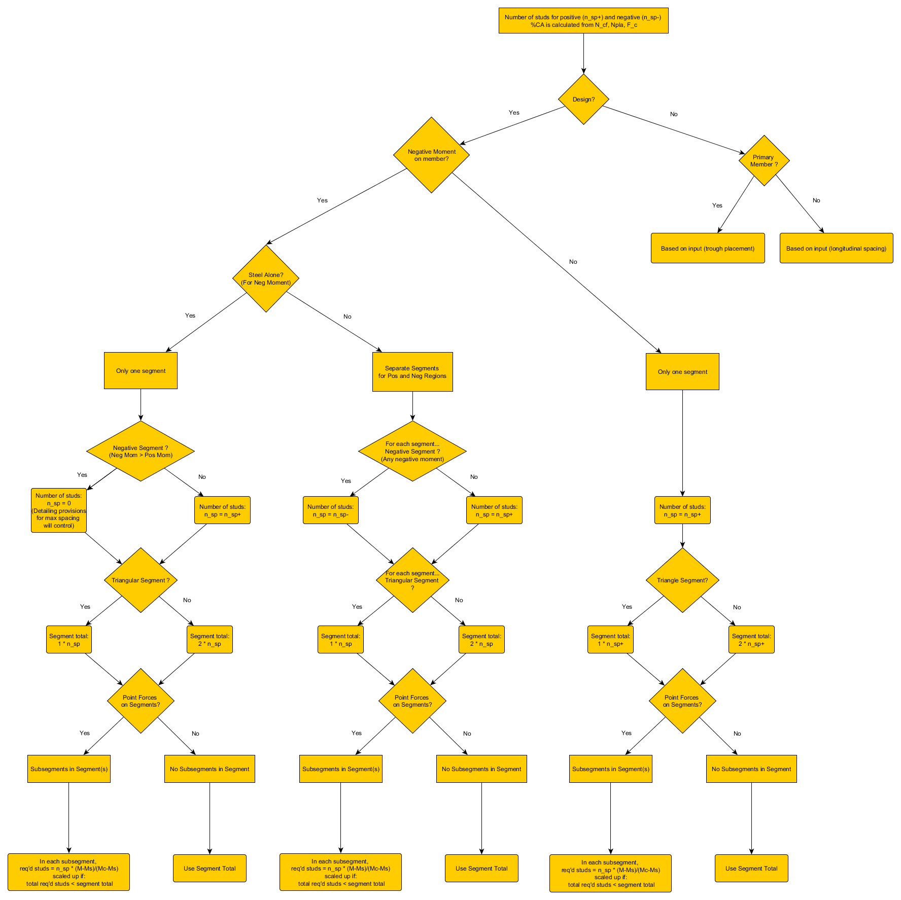
The design philosophy for the number and the placement of studs varies between secondary and primary members. Because secondary members have spacing limitations caused by their orientation to the profiled sheeting (i.e. perpendicular to the sheeting), the stud placement is first determined and the composite action is subsequently calculated based on the number of studs from zero to maximum moment. With primary members, the number of studs is calculated directly from the composite action applied to the member and the stud placement is subsequently determined (as outlined below).
The design of the number of studs and layout of the studs along a member is always performed for the member using current parameters that exist in the model at the time the form is run. (As opposed to the optimized parameters which may be found during the optimisation).
Secondary Members
Members modelled perpendicular to the profiled sheeting are considered secondary members. In general, loads applied to and generated from the composite deck, are first transferred to the secondary members before transferred to primary members.
Since secondary members are perpendicular to the profiled sheeting, the placement of the studs is limited by the spacing of the ribs. To accommodate this, the program first attempts to position the studs according the to rib spacing according to the methodology found in the following section.
Determination of stud placement
The program attempts to position the studs according the to rib spacing as follows:
I- It considers four possible stud placement scenarios: (i) Two studs per rib, (ii) One studs per rib, (iii) One stud in every other rib, and (iv) One stud in every second rib.
II - A controlling segment of the member is found. For members with multiple segments (i.e. a member which has both positive and negative moment) it finds and uses the longest positive segment that is greater than 5% of the entirely length of the member. If no positive segment is greater than or equal to 5% of the length of the member, the longest negative segment is used. If the member has only one segment (i.e. the moment is entirely positive or entirely negative), it uses the single segment.
III - Once the controlling segment is found, it finds the shortest distance between the maximum moment and zero moment in that segment. For each of the four stud placement scenarios, the number of studs that will exist over this distance is determined and is used to calculate the degree of composite action for each scenario.
III - Each of the four stud placement scenarios is evaluated. Any scenario which either has a degree of composite action lower than the minimum allowed composite action or has a spacing of studs greater than the maximum allowed spacing or smaller than the minimum allowed spacing is eliminated. If only one row of studs is allowed (due to input of "Number of rows" set to "1" or transverse spacing conditions not being met), scenario (i) is eliminated. Furthermore, if two rows of studs are allowed, but scenarios (i) and (ii) both result in the same composite action (most often 100%), scenario (i) is eliminated as it is less efficient.
IV - After eliminating the disqualified stud placement scenarios, the remaining ones are evaluated to see which scenario has a degree of composite action closest to that assigned to the member. If none of the stud placement scenarios are qualified, scenario (ii) ( "One stud per rib") is used by default.
Effect of stud placement on composite action
For secondary members, the composite action(s) determined by the chosen stud placement scenario is used in the ULS final stage checks. For members which have one segment (entirely positive or entirely negative moment), there is a single degree of composition action on the member which is used in the checks. For members with multiple segments (both positive and negative), the value for composite action will vary from segment to segment depending on the number of studs from zero to maximum moment and the values of Nc,Rd and Npl,a (minimum of the compressive strength of the concrete and the tensile strength of the steel section) for positive segments and of Fs and Npl,a (minimum of the tensile strength of the steel reinforcement and the compressive strength of the steel section) for negative segments. The overall composite action on the member is the one associated with controlling segment (as determined in the previous section). If the maximum unity check for bending in the final stage checks comes from a segment other than the one from which the overall composite action comes, then the composite action for that segment is used for the bending check and is also shown in the detailed output.
Primary members
Members modelled parallel to the profiled sheeting are considered primary members.
Number of studs
Before any attempt to position the studs along the composite member, the program first determines the number of studs needed from zero to maximum moment in the positive and negative moment regions based on the degree of composite action assigned to the member. The number of studs needed in the negative moment regions in only considered when “Negative flexural strength determined using steel section alone” is set to “No”.
For the number of studs needed in the positive moment region, the minimum of the compressive strength of the concrete and the tensile strength of the steel section is multiplied by the target degree of composite action, and divided by the shear strength of a single stud. This number is then rounded up to determine the number of studs between zero and maximum positive moment.

Where:

|
Compression resistance of concrete flange |

|
Tension resistance of steel member |
The following paragraph only applies when “Negative flexural strength determined using steel section alone” is set to “No”:
For the number of studs needed in the negative moment region, the minimum of the tensile strength of the steel reinforcement and the compressive strength of the steel section is multiplied by the target degree of composite action, and divided by the shear strength of a single stud. This number is then rounded up to determine the number of studs between zero and maximum negative moment.

Where:

|
Tension resistance of reinforcement |

|
Compression resistance of steel member |
Stud Layout: Uniformly Loaded Simple Span Members
For members which are uniformly loaded and have pinned ends, where the moment along the member is positive and the maximum moment occurs at or close to the mid-span, the number of studs needed in the positive moment region (Nstuds+) is doubled to attain the total number of studs. These studs are uniformly distributed along the length of the member. The number of studs may be increased to meet maximum spacing requirements if needed.
Stud Layout: Segmented Members
Members which either support point loads, such as girders, or have both positive and negative* moment, such as fixed-end members, may require an uneven distribution of studs in order to develop the required strength at different locations along the member. To do this, the program divides the member into segments and/or sub-segments. Any transition from a negative* to positive moment, or vice versa, initializes a new segment on the member. Any point load will initialize a new sub-segment within the segment in which it is found.
Members which have a segmented stud layout are also given a uniform stud layout. This uniform layout uses the minimum stud spacing of all segments and sub-segments and extrapolates the number of studs along the entire beam using this spacing.
(* A transition from positive to negative moment, or vice-versa, only initializes a new segment if Negative flexural strength determined using steel section alone is set to “No”)
Members with Both Negative and Positive Moment
For members with both negative and positive moment, the number of studs in a positive region segment is based directly on the number of studs determined by the target degree of composite action (Nstuds+). When “Negative flexural strength determined using steel section alone” is set to “No”, the number of studs in the segment for the negative region is based directly on the number of studs determined by the target degree of composite action (Nstuds-).
If the segment is one in which the moment value increases from zero to a maximum moment and then decreases back to zero, the number of studs in the segment is approximately equal to two times the number of studs. If the segment is one in which the moment value is triangular (i.e. it only increases or decreases), the number of studs in the segment is approximately equal to one times the number of studs.
Members with Point Forces
For members which support point forces, the segment(s) in which the point force(s) exist are further divided into sub-segments. The number of studs needed in each sub-segments is determined as follows:

Where:

|
Number of studs required in the sub-segment |

|
Number of studs required between zero and maximum moment |

|
Difference between the maximum and minimum moment in the sub-segment |

|
Moment resistance of steel beam alone |

|
Moment resistance of the composite beam at the target degree of composite action |
After the number of studs required in each sub-segment has been calculated, the percentage of studs required in each sub-segment relative to the total number of studs required in all sub-segments is used to distribute the studs according to the total number of studs in the segment as determined by the target degree of composite action on the member. This ensures that the total number of studs on the member matches the total number of studs expected according to the degree of composite action. In cases where the member is over-designed, the number of studs in each segment will be greater than required. In cases where the beam size and target degree of composite action have already been optimized, the number of studs in each segment will be equal to or close to the number required.
Spans Composed of Multiple Members
The stud design works best when a span consists of a single member with a constant cross-section. If the span is composed of multiple members, the program attempts to distribute the studs but results should not be considered reliable. Particularly, if the span has 3 or more members, the middle member(s) will generally not have any zero moment. For these members a stud layout diagram will not be displayed and the number of studs will be shown as 'N/A'.
Number of rows of studs
The program allows studs to be designed in either one or two rows across the width. To allow two rows of studs, set the value of "Number of Rows" in the setup to "2". If two rows are allowed, the program will first check to see if two rows are allowed on the section. Two rows are allowed if the spacing between the studs is greater than or equal to four times the stud diameter, with a distance to the edge of the flange of at least 1 inch or one times the stud diameter, whichever is greater. If two rows can be used, the program will design the studs with two rows only if needed based on the minimum spacing requirements.
Results and output
Result Values
Three result values contain information regarding the number of studs on a member: "Label Uniform (LU)", "Label Segmented (LS)", and "Total Studs (TS)". The first two contain additional information about the cross-section and camber, while the total studs result is simply a numerical value.
For members which have only one segment and no sub-segments (i.e. no negative composite action and no point forces exist on the member) , the studs can be positioned uniformly along the length of the member. In this case, the segmented result "Label Segmented (LS)" is simply set equal to the uniform result and the "Total Studs (TS)" is equal to the uniform number of studs.
For members which have multiple segments or sub-segments, the studs in each segment or sub-segment are first calculated. The "Label Segmented (LS)" contains the studs in each segment or sub-segment separated by commas. Next, the closest spacing of studs is determined and extrapolated over the length of the member to get the uniform number of studs for the "Label Uniform (LU)". The "Total Studs (TS)" is the sum of the studs all segments or sub-segments.
Output
A table with the number of studs in each segment and/or sub-segment as well as a diagram showing the layout of the studs is displayed at the end of the detailed and standard layouts.
On the stud layout diagram, the uniform number of studs is displayed at the top of the stud layout diagram and the segmented number of studs is shown at the bottom (as needed). Additionally, for secondary members which are perpendicular to the ribs of the profiled sheeting, the number of ribs available (either for the entire beam for the uniform studs, or in each segment or sub-segment for segmented studs) is also displayed.