ULS final stage - stiffened openings
The calculation is based on the publication SCI P355 - Design of composite beams with large web openings, R. M. Lawson, S. J. Hicks published in 2011.
The topic shows below only info specific to stiffened openings and modifications in calculations compared to openings without stiffeners.
Horizontal stiffeners are ment to be formed from rectangular plates, welded to the top and /or the bottom edges of the openings, on one or both sides. The input of the openings stiffeners may be done through "Member1D opening" dialog. The stiffeners are currently only used by the composite check.
Opening reinforcement group in the dialog is available if all conditions below are fulfilled:
- shape is not set to Cross-section.
- steel and concrete material are activated in the project
- composite beam module from CADS is not activated
- valid license is present
- opening is defined on a beam with steel material and Structure type of the member is plate rib (this condition is neglected during the input of the opening, when the target beam is not known)
Geometric recommendations
Chapters 5.2.1-2 specifies general geometry recommendations for openings with horizontal stiffeners. The list of tested recommendations may be seen below:
- The br/tr ratio of the stiffeners should not exceed the limits for a Class 3 section (br/tr ≤ 10*ε). Since the beam is designed as a Class 1 or 2 section, then any part of the outstand in excess of the Class 2 limit is considered as ineffective. (br ≤ 10*tr*ε)
-
Area of the stiffener (independent if single or double sided) Ar ≤ 0,5*ho* tw
-
Distance to the inner surface of the flange ≥ 50mm
-
Minimum offset from opening ≥ 8mm
-
8mm ≤ Thickness of the stiffener tr ≤ 20mm
-
80 mm or lo/10 ≤ Width of the stiffener br ≤ MIN (10*tr*ε, 200mm)
-
Weld throat thickness a ≥ MAX (0,5*tr, 5mm)
-
Distance between studs ≤ 300mm
-
Length of the opening lo ≤ 2,5*ho
- Anchorage length lv of the stiffener beyond each end of the opening should generally be taken as not less than 0.25*lo or 2*br or a minimum of 150 mm and should satisfy the following criteria given by expressions (55):
For shear resistance of the fillet welds:
For shear resistance of the stiffeners:
For shear resistance of the web
with:
h - height of steel cross-section
n - number of stiffeners (single-sided = 1, double-sided = 2)
br - width of stiffener
tr - thickness of stiffener
tw - thickness of the web
ho - height of opening
lo - length of opening
Ar - cross-sectional area of stiffener Ar = n*tr*MIN(br;10*tr*ε)
Fr - design force in stiffener Fr = Ar * fyr / γM0
fyr - yield strength of stiffener material
fvw,d - design shear strength of a fillet weld. Material of fillet weld is assumed to be the same as the material of the stiffener.

fur - ultimate strength of stiffener material
fub - ultimate strength of beam material
βw - correlation factor for fillet welds (EN 1993-1-8, Table 4.1)
γM0 - partial safety factor
γM2 - partial safety factor for welds
Chapter 5.2.3 specifies additional geometry recommendations for openings with single-sided horizontal stiffeners. The list of tested recommendations may be seen below:
-
Web depth thickness tw ≤ 70*ε
- Anchorage length lv should be taken as MIN (2br, so - the distance to the edge of the adjacent opening) and should satisfy the limits in expression (55).
- Stiffener width br ≤ lo/6 for fabricated beams and lo /4 for rolled beams
-
Thickness of the stiffener tr should satisfy the following limit:

Not fulfilling any of the recommendations will cause a general warning to be displayed.
Global bending
Resistance
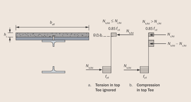
To determine the plastic bending resistance at the centreline of the opening, the forces in the Tees and the slab must be in equilibrium. Two situations are possible: with the plastic neutral axis in the slab and with the plastic neutral axis in the top Tee.
The possible cases of plastic stress blocks in a perforated composite beam:
Resistance of concrete slab including the resistance of shear studs is given as:

with:
fcd - design resistance of concrete in compression ( = fck/γc)
beff,o - effective width of the composite beam at opening
nsc - number of shear connectors placed over the distance from the nearer support to the centreline of the opening
PRd - design resistance of the shear connectors used with profiled sheeting
Resistance of bottom Tee in tension is given as:

with:
AbT - cross-sectional area of bottom Tee
Ar - cross-sectional area of stiffener
Case 1: Nc,Rd ≥ NbT,Rd
The compression resistance of the full thickness of the slab at the position of the opening is the lesser of the compression resistance of the effective width of slab and the resistance provided by the shear connectors between the end of the beam and the centreline of the opening. In this case plastic neutral axis is in the concrete slab.
The plastic bending resistance is then given by:

with:
heff - effective depth of the beam between the centroids of the Tees (stiffener area included in the calculation)
zt - depth of the centroid of the top Tee from the outer edge of the top flange (stiffener area included in the calculation)
zc - depth of concrete in compression

The axial force in bottom Tee is calculated as:

with:
MEd - design bending moment at opening
Case 2: Nc,Rd < NbT,Rd
In this case, the compression resistance of the full depth of the effective width of slab is less than the tension resistance of the bottom Tee and equilibrium is achieved by developing compression in the top Tee. For this situation, it is conservative to assume that the top Tee is uniformly stressed and subject to a force equal to the difference between the tension resistance of the bottom Tee and the compression resistance of the slab, i.e. it provides a resistance equal to NbT,Rd − Nc,Rd. In this case plastic neutral axis is in steel Top tee.
The compression resistance of unstiffened top Tee is limited by cross-section class 2 limit, thus:

with:
AtT - cross-sectional area of compressed top Tee for global bending (Tee is assumed to be class 2)
hwt - height of the web out stand of a top Tee

hw - clear distance between flanges of unperforated section
ho - height of opening
eo - eccentricity of opening
The plastic bending resistance is then given by:

with:
zc - depth of concrete in compression ( = hc)
To determine the axial force in the bottom Tee for this case, expression from Case 1 should be used unless this gives NbT,Ed > Nc,Rd. In such case the force may be taken as:

As given by SCI P355 Article 3.2.4, for the composite design of beams with large openings close to the supports, it is likely that a shear connection resistance equal to 40% of the tensile force developed in the bottom Tee (i.e. Nc,Rd ≥ 0.4*NbT,Ed) will be required to ensure adequate composite bending resistance. If this is not achieved by the application of current minimum degree of shear connection rules, then additional shear connectors should be provided for critical parts of the span or composite action should be neglected when calculating the global bending resistance at opening locations with an inadequate number of shear connectors.
In such a case the contribution of concrete is neglected in the calculation of bending resistance:

To determine the axial force in the bottom Tee for this case only steel section is used:

If the design bending moment MEd is greater than the given resistance Mo,Rd, the status of this check is set to "Not OK" and the warning that " The bending moment resistance of the section is not adequate." is displayed.
Vierendeel bending
Bending resistance of Tee
Classification of a Tee
The web is assumed to be Class 2 when stiffened, therefore no reduction of Tee height is not performed.
Resistance
Vierendeel bending is the means by which shear force is transferred across a large opening. The sum of the Vierendeel bending resistances at the four corners of the opening, plus the contribution due to composite action between the top Tee and the slab, must therefore not be less than the design value of the difference in bending moment from one side of the opening to the other due to that shear force; this may be expressed as:

with:
MbT,NV,Rd - bending resistance of the bottom Tee, reduced for coexisting axial tension and shear
MtT,NV,Rd - bending resistance of the top Tee, reduced for coexisting axial tension and shear
Mvc,Rd - local composite Vierendeel bending resistance
VEd - design value of the vertical shear force (taken as the value at the lower moment side of the opening)
le - effective length of the opening for Vierendeel bending
The plastic bending resistance of a top or bottom Tee section in the absence of axial force (including possible reduction due to vertical shear) is given by the following expression, assuming that the plastic neutral axis is in the flange of the Tee:

with:
Aw,T - cross sectional area of web of the respective Tee ( = hw,T*tw)
hw,T - depth of web of the respective Tee
Af - cross sectional area of the flange
tf - thickness of the steel flange
bf - width of the steel flange
Ar - cross-sectional area of stiffener
er - is the offset distance of centre of stiffener from tip of web
zpl - distance between the plastic neutral axis in the flange and top of the flange

Similar formula assuming that the plastic neutral axis is in the web of the Tee:

with:
zpl - distance between the plastic neutral axis in the web and bottom of the flange

Influence of normal force
The reduction of plastic bending resistance for co-existent axial force may be determined according to the following approximate formulas:
For top Tee:

For bottom Tee:

with:
Mpl,V,Rd - bending moment resistance of a Tee including possible reduction from vertical shear
Mpl,NV,Rd - bending moment resistance of a Tee including possible reduction from vertical shear and axial force
Npl,Rd - axial resistance of the Tee
NEd - design value of the axial force in the Tee due to the global bending action, either the compression force in the top Tee or the tension force in the bottom Tee.
Top Tee:
For Case 1 NEd= 0 and for Case 2: NEd= max(NbT,Rd - Nc,Rd).
Bottom Tee:
NEd= NbT,Rd
Local composite resistance
A contribution to the Vierendeel bending resistance occurs due to local composite action of the top Tee with the slab.The bending resistance due to composite action of the top Tee with the slab is given
conservatively by:

with:
ΔNc,Rd -compression force developed by the shear connectors placed over the opening (= nsc,o*PRd)
nsc,o - number of shear connectors placed over the opening
PRd - design resistance of the shear connectors used with profiled sheeting
zt - depth of the centroid of the top Tee from the outer edge of the flange (as an approximate = tf)
ko - reduction factor due to the flexibility of the opening, which takes account of second order effects together with the combination of shear and tension forces at the edge of the opening, generally given as below, but take as 1.0 if lo ≤5*hwt

lo - length of opening
hwt - depth of the top Tee
If the design effect of Vierendeel bending is greater than the given resistance, the status of this check is set to "Not OK" and the warning that " The bending moment resistance of the section is not adequate." is displayed.