Theoretical background - method of iterative procedure for check of response used in SCIA Engineer
The check response is based on the calculation of strain and stress in particular component (concrete fibre, reinforcement bar) and comparison with limited values with respect of NBR requirements. Based on the internal forces, concrete cross-section and defined reinforcement by the user, SCIA Engineer is able to calculate the response of a member or a single cross-section. This method uses an iteration routine to calculate equilibrium based on the internal forces, the cross-section, material properties and reinforcement layout. However, this method does not calculate extremes (capacities of cross-section) like the interaction diagram, but calculates the state of equilibrium for that section (response). The calculation also includes depth of compression zones (d), curvatures in each axis (x, y and z), stresses, strains and forces in particular components. Generally, this iterative method works for the interaction of the normal force (N) with uni-axial or bi-axial bending moments (My + Mz).
Assumptions and limitations
There are the following assumptions:
- Strain and stress of diagram defined in properties of material will be used
- Concrete – parabola-rectangular stress-strain diagram
- Reinforcement – bilinear without inclined horizontal branch stress-strain diagram
- Tensile stress in concrete is not considered
- Standard REDES reinforcement is considered
- The area of longitudinal reinforcement is not subtracted from concrete area
Calculation procedure
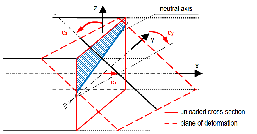
Imagine a diagram representing the strain in a reinforced concrete cross-section. Generally, the cross-section can be non-symmetric to y or z axis and loaded with a combination of N, My and Mz. Then the vector of strain consists of three nonzero values ε = {εx; εy, εz}. This vector determines so called plane of deformation (see following figure).
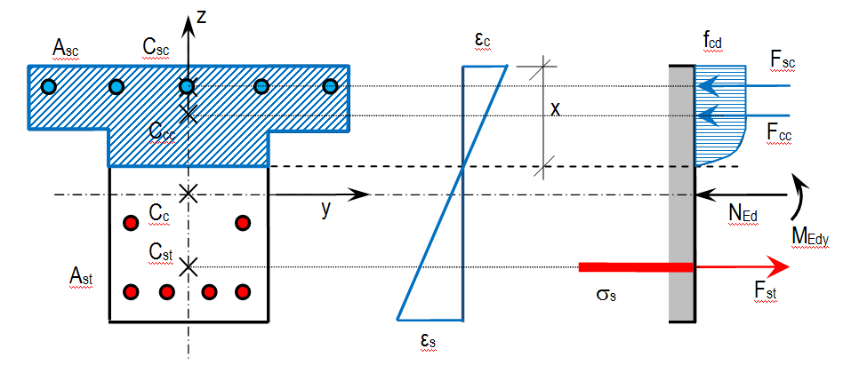
Corresponding plane of strain for plane of equilibrium in one plane bending only (My) is shown in following figure. Nevertheless, the distribution of the stress in compression part depends on type of stress-strain diagram of concrete. In case of parabola-rectangular diagram the stress distribution is constant or linear-parabola.
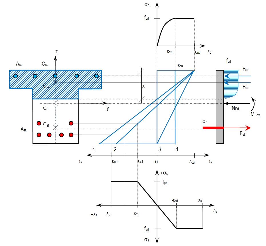
The previous figure shows a non specific case, but let us imagines an ultimate state. Under the ultimate state, we understand a case, where either concrete or steel is strained to limit value. We can draw some cases in a similar diagram. The basic assumptions of this limit strain method show the following figure. Generally, four limit strain states can occur. The numbering (1-4) in the following figure represents particular state types of the cross-section. The state (1) corresponds to the optimal failure when ultimate compressive strain in concrete (εcu) and ultimate tensile strain in reinforcement (εu) are reached. In case of state (2), the ultimate limit strain in concrete is assumed within considering the strain in reinforcement at the beginning of plastic branch (εs1 = fyd / Es). The state (3) expresses the starting of the concrete crushing. Finally, the state (4) represents the reaching of ultimate compressive strain for axially loaded member decreased due to brittle failure effect.
The following checks are performed
Check of compressive concrete

|
verification of strains |

|
verification of stresses |
Check of compressive reinforcement

|
verification of strains |

|
verification of stresses |
Check of tensile reinforcement

|
verification of strains |

|
verification of stresses |
Unity check is maximum from all partial unity checks. It means