Concrete setup
Generally, the known items from the past Concrete setting (structure) and Design defaults have been merged together into one item Concrete setup. if you go to view Complete setup you can see Design defaults and Concrete settings as two main subgroups.
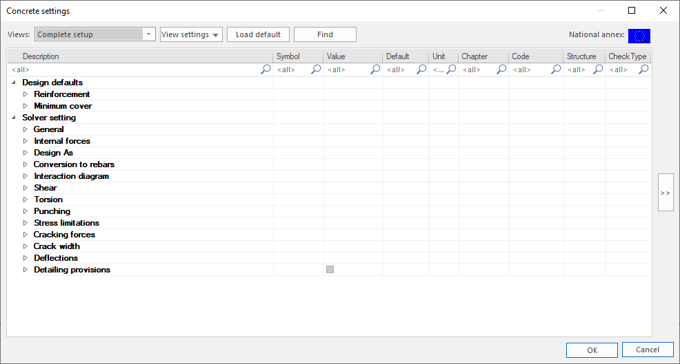
Solver settings
General
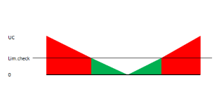
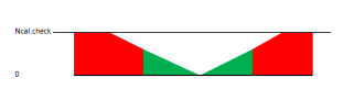
Limit value of unity check
| Description |
Limit value of unity check when the check is still OK |
| Default | Edit box; default = 1,0 |
|
Code |
- |
| Level | Standard |
|
Figure |
|
| Member | All |
Limit value of unity check cannot be changed from 1,0
Value of unity check for not calculated unity checks
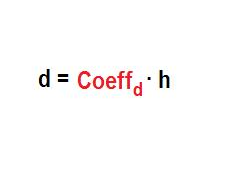
The coefficient for calculation effective depth of cross-section
| Description |
The coefficient for calculation effective depth of cross-section from depth of cross-section, if effective depth of cross-section is not possible to calculate from plane of equilibrium (tensile reinforcement or compressive concrete fibre was not found) |
| Default | Edit box; default Coeffd = 0,9 |
|
Code |
- |
| Level | Advanced |
|
Figure |
|
| Member | All |
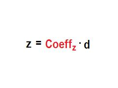
The coefficient for calculation of inner lever arm
| Description |
The coefficient for calculation inner lever arm from effective depth of cross-section, if effective inner lever arm is not possible to calculate from plane of equilibrium (tensile reinforcement or compressive concrete fibre was not found) |
| Default | Edit box; Coeffz = 0,9 |
|
Code |
- |
| Level | Advanced |
|
Figure |
|
| Member | All |
The coefficient for calculation force, where member as under compression
| Description |
The coefficient for calculation force, where member is considered as under compression. If NEd ≤ Ncom → member under compression |
| Default | Edit box; Coeffcom = 0,1 |
|
Code |
- |
| Level | Advanced |
|
Figure |

|
| Member | All |
Creep
Type input of creep coefficient
| Description |
Type of calculation creep coefficient: - Auto - creep coefficient is calculated automatically by the program - User value - creep coefficient inputted directly by the user |
| Default | Combo box; Type φ = Auto |
|
Code |
Annex B.1 |
| Level | Standard |
|
Figure |
- |
| Member | All |
Relative humidity
| Description |
Relative humidity of ambient environment |
| Default | Edit box; RH = 50 % |
|
Code |
Annex B.1 |
| Level | Advanced |
|
Figure |
- |
| Member | All |
Age of concrete at loading
| Description |
Age of concrete at loading of the member |
| Default | Edit box; t0 = 28 days |
|
Code |
Annex B.1 |
| Level | Advanced |
|
Figure |
- |
| Member | All |
Age of concrete at the moment considered
| Description |
Age of concrete at the moment considered. It means, time, which creep coefficient is calculated for. |
| Default | Edit box; t = 18250 days |
|
Code |
Annex B.1 |
| Level | Advanced |
|
Figure |
- |
| Member | All |
User value
| Description |
User defined value of creep coefficient |
| Default | Edit box; φ = 2,5 |
|
Code |
Annex B.1 |
| Level | Standard |
|
Figure |
- |
| Member | All |
SLS
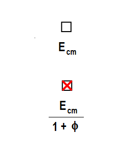
Use effective modulus of concrete
| Description |
Possibility to use effective E modulus of concrete. It means the long-term behaviour of concrete is covered in the analysis of the crack width, stress limitations and stiffness calculation. |
| Default | Check box, default False |
|
Code |
7.1(2) |
| Level | Advanced |
|
Figure |
|
| Member | All |
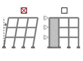
Default sway type
Sway around y axis
| Description |
Yes indicates, that the members are prone to sway (unbraced) around y axis of LCS of the member. This setting is used in calculation of slenderness and internal forces 1D, if in Buckling data or Buckling data library if possibility “Setting” is selected. |
| Default | Check box ; Default True |
|
Code |
- |
| Level | Standard |
|
Figure |
|
| Member | All |
Sway around z axis
| Description |
Yes indicates, that the members are prone to sway (unbraced) around z axis of LCS of the member. This setting is used in calculation of slenderness and internal forces 1D, if in Buckling data or Buckling data library if possibility “Setting” is selected. |
| Default | Check box ; Default True |
|
Code |
- |
| Level | Standard |
|
Figure |
|
| Member | All |
Internal forces
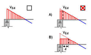
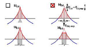
Shear force reduction above supports
| Description |
Shear force above support is reduced if this item is ON. |
| Default | Check box; default False |
|
Code |
6.2.1(8) |
| Level | Advanced |
|
Figure |
|
| Member | Beam, Beam slab, Rib |
Moment reduction above supports
| Description |
Bending moment above support is reduced if this item is set ON: - for standard support, formula 5.9 is used - for column support the reduced moment is the same as on the face of the column |
| Default | Check box; default False |
|
Code |
5.3.2.2(4) |
| Level | Advanced |
|
Figure |
|
| Member | Beam, Beam slab, Rib |
Shifting of moment curve to cover additional tensile forces caused by shear
| Description |
If the check box is ON, the additional tensile force caused by the shear force is taken into account using the shift rule. |
| Default | Check box; default True |
|
Code |
9.2.1.3(2) |
| Level | Standard |
|
Figure |
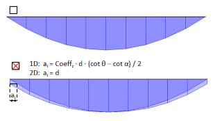
|
| Member | Beam, Rib, Plate, Shell(Plate) |
Geometric imperfection ULS
| Description |
The geometric imperfection is taken into account for calculation first order eccentricity, if this parameter is ON. |
| Default | Check box; default True |
|
Code |
5.2(5) |
| Level | Standard |
|
Figure |
|
| Member | Column |
Geometric imperfection SLS
| Description |
The geometric imperfection is taken into account for calculation first order eccentricity, if this parameter is ON. |
| Default | Check box; default False |
|
Code |
5.2(5) |
| Level | Standard |
|
Figure |
|
| Member | Column |
Bow imperfection e0,y
| Description |
Setting to define local bow imperfections on the member. |
| Default | EN 1992-1-1 art. 5.2(9) |
|
Code |
5.2(9) |
| Level | Standard (only visible if the functionality "initial imperfections" is activated) |
|
Figure |
|
| Member | 1D (Beam, Beam slab, Column, Rib) |
Bow imperfection e0,z
| Description |
Setting to define local bow imperfections on the member. |
| Default | EN 1992-1-1 art. 5.2(9) |
|
Code |
5.2(9) |
| Level | Standard (only visible if the functionality "initial imperfections" is activated) |
|
Figure |
|
| Member | 1D (Beam, Beam slab, Column, Rib) |
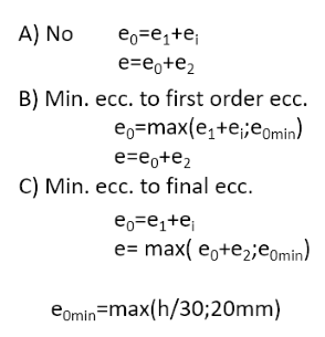
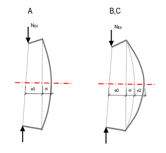
Minimum eccentricity
| Description |
The minimum value of the eccentricity can be set as follows: A) Switched OFF, no minimum value is accounted for B) The minimum is considered for the calculation of the first order eccentricity C) The minimum is considered for the final value of the eccentricity e1 - first order moment eccentricity e2 - second order moment eccentricity ei - eccentricity caused by imperfection |
| Default | Check box; default True |
|
Code |
6.1.4 |
| Level | Advanced |
|
Figure |
|
| Member | Column |
First order eccentricity with the equivalent moment
| Description |
The first order moment is taken into account as equivalent first order moment, if this parameter is ON. |
| Default | Check box; default True |
|
Code |
5.8.8.2(2) |
| Level | Advanced |
|
Figure |
|
| Member | Column |
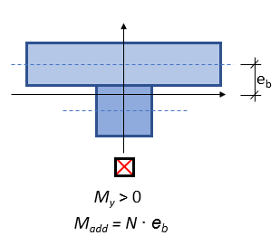
Second order eccentricity
| Description |
The second order eccentricity can be set as follows:
|
| Default | Combo box; default Nominal curvature |
|
Code |
5.8.5 |
| Level | Standard |
|
Figure |
|
| Member | Column |
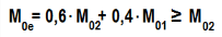
Effective creep ratio coefficient M0Eqp/M0Ed
Internal forces modifications
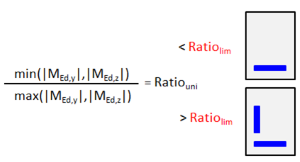
Limit ratio of bending moment for uni axial method
| Description |
Limit ratio of bending moments for using uniaxial design method. If ratio of bending moments is lesser than limit ratio, uniaxial design method is used and smaller value of bending moment and shear force is neglected. |
| Default | Edit box; ρM,lim = 0,1 |
|
Code |
- |
| Level | Advanced |
|
Figure |
|
| Member | 1D (Beam, Beam slab, Column, Rib) |
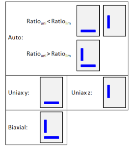
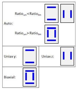
Determination of unfavourable direction
| Description |
Determination of the direction for calculation of second order effect and geometrical imperfection effect and geometrical imperfection according to conditions 5.38a a 5.38b. Auto - automatic calculation of direction for taking into account second order effect and geometrical imperfection according to conditions 5.38a a 5.38b. Uniaxial - second order effect and geometrical imperfection is taken into account only in one (more unfavourable direction). Biaxial - second order effect and geometrical imperfection is taken into always in both directions. |
| Default | Combo box; default = Auto |
|
Code |
5.8.9 |
| Level | Advanced |
|
Figure |
|
| Member | Column |
Neglect normal forces in rib
| Description |
If the checkbox ON, normal forces in ribs are neglected. Additional bending moment corresponding to the recalculation to the centre of gravity of the whole rib cross-section is added if the bending moment is positive. |
| Default | Check box; default False |
|
Code |
- |
| Level | Advanced |
|
Figure |
|
| Member | Rib |
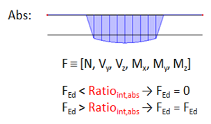
Absolute limit ratio for modification of internal forces
| Description |
Internal forces will be set to zero if the modification of internal forces using the absolute limit ratio is taken into account and the internal forces are smaller than the input value. |
| Default | Edit box; Ratioint,abs = 5,0 kN |
|
Code |
- |
| Level | Standard |
|
Figure |
|
| Member | 1D (Beam, Beam slab, Column, Rib) |
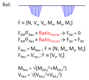
Relative limit ratio for modification of internal forces
| Description |
Internal forces will be set to zero if the modification of internal forces using the relative limit ratio is taken into account and the ratio of internal forces and resultant of bending moments (for N, My, Mz, T) or resultant of shear forces (for Vy, Vz) is smaller than the input value. |
| Default | Edit box; Ratioint,rel = 0,1 |
|
Code |
- |
| Level | Standard |
|
Figure |
|
| Member | 1D (Beam, Beam slab, Column, Rib) |
Modification of internal forces
| Description |
Internal forces used in concrete calculation are modified. No - internal forces are without modification Absolute ratio - internal forces will be set to zero if internal forces are smaller than the absolute limit ratio. Relative ratio - internal forces will be set to zero, if ratio of internal forces and resultant of bending moments (for N, My, Mz, T) or resultant of shear forces (for Vy, Vz) is smaller than the relative limit ratio. |
| Default | Combo box; default = No |
|
Code |
- |
| Level | Standard |
|
Figure |
|
| Member | 1D (Beam, Beam slab, Column, Rib) |
Design method (beams)
| Description |
Method for design of longitudinal reinforcement for beams. Auto - Automatic determination of design method according to bending moments ratio ρM. Uniaxial around z - Design for uniaxial bending moment Mz only. Moment My will not be taken into account (My = 0 kNm). Uniaxial around y - Design for uniaxial bending moment My only. Moment Mz will not be taken into account (Mz = 0 kNm). Biaxial - Design for biaxial bending for both bending moments My and Mz. |
| Default | Combo box; default = Auto |
|
Code |
- |
| Level | Advanced |
|
Figure |
|
| Member | Beam, Beam slab, Rib |
Design method (columns)
| Description |
Method for design of longitudinal reinforcement for columns. Auto - Automatic determination of design method according to bending moments ratio ρM. Uniaxial around z - Design for uniaxial bending moment Mz only. Moment My will not be taken into account (My = 0 kNm). Uniaxial around y - Design for uniaxial bending moment My only. Moment Mz will not be taken into account (Mz = 0 kNm). Biaxial - Design for biaxial bending for both bending moments My and Mz. |
| Default | Combo box; default = Auto |
|
Code |
- |
| Level | Advanced |
|
Figure |
|
| Member | Column |
Design As
Coefficient for reduction of strength of the concrete in compressive concrete
| Description |
Coefficient for reduction of strength of the concrete in compressive concrete which is used for calculation design value of resistance of concrete compressive strut nRd = Acc · Redfcd · fcd |
| Default | Edit box; default Redfcd = 0,85 |
|
Code |
- |
| Level | Standard |
|
Figure |
- |
| Member | All |
Beam, Column, Rib, Beam Slab
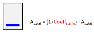
Coefficient increasing statically required reinforcement in beam for upper surface
| Description |
Increasing statically required reinforcement at upper surfaces for beam, beam slab and rib. |
| Default | Edit box; Coeffstat.up = 0,0 |
|
Code |
- |
| Level | Advanced |
|
Figure |
|
| Member | Beam, Beam slab, Rib |
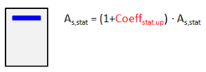
Coefficient increasing statically required reinforcement in beam for lower surface
| Description |
Increasing statically required reinforcement at lower surfaces for beam, beam slab and rib. |
| Default | Edit box; Coeffstat.lo = 0,0 |
|
Code |
- |
| Level | Advanced |
|
Figure |
|
| Member | Beam, Beam slab, Rib |
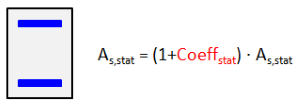
Coefficient increasing statically required reinforcement in column
| Description |
Increasing statically required reinforcement for column. |
| Default | Edit box; Coeffstat = 0,0 |
|
Code |
- |
| Level | Advanced |
|
Figure |
|
| Member | Column |
Design longitudinal and shear reinforcement due to torsion
| Description |
Longitudinal and shear reinforcement due to torsion is not designed if the check box is set False |
| Default | Check box; default = True |
|
Code |
- |
| Level | Advanced |
|
Figure |
|
| Member | 1D (Beam,Beam slab,Column,Rib) |
Plate, Wall, Shell(Plate), Shell(Wall), Deep Beam
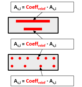
Coefficient for increasing the statically required area of reinforcement for the upper surface of Plate, Shell(Plate)
| Description |
Increasing statically required reinforcement for upper surface of Plate, Shell(Plate). As,stat = (1 + Coeffstat.up.2D) ∙ As,stat |
| Default | Edit box; Coeffstat.up.2D = 0,0 |
|
Code |
- |
| Level | Advanced |
|
Figure |
- |
| Member | Plate, Shell(Plate) |
Coefficient for increasing the statically required area of reinforcement for the lower surface of Plate, Shell(Plate)
| Description |
Increasing statically required reinforcement for lower surface of Plate, Shell(Plate). As,stat = (1 + Coeffstat.lo.2D) ∙ As,stat |
| Default | Edit box; Coeffstat.lo.2D = 0,0 |
|
Code |
- |
| Level | Advanced |
|
Figure |
- |
| Member | Plate, Shell(Plate) |
Coefficient for increasing the statically required area of reinforcement for both layers in Wall, Shell(Wall) and Deep Beam
| Description |
Increasing the statically required reinforcement for both surfaces of Wall and Shell(Wall). As,stat = (1 + Coeffstat.both.2D) ∙ As,stat |
| Default | Edit box; Coeffstat.both.2D = 0,0 |
|
Code |
- |
| Level | Advanced |
|
Figure |
- |
| Member | Wall, Shell(Wall), Deep beam |
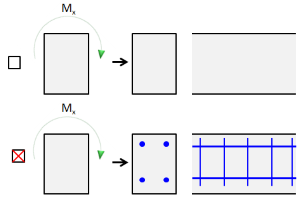
(TO-DO- KRS) -Conversion to rebars
Unify upper reinforcement above middle support
...
Type of zone for corrected reinforcement
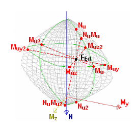
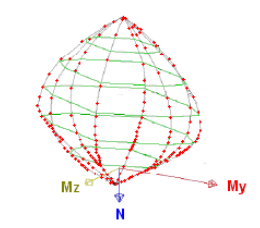
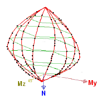
Interaction diagram
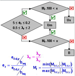
Interaction diagram method
| Description |
Possibility to set method for evaluation of results using interaction diagram: - NRd - assuming MEd is constant - MRd - assuming NEd is constant - NRdMrd - assuming eccentricity is constant - Mrdy - assuming MEdz is constant - Mrdz - - assuming MEdy is constant |
| Default | Combo box; default = NRdMRd |
|
Code |
6.1 |
| Level | Standard |
|
Figure |
|
| Member | All |
Division of strain
| Description |
Calculation precision for one of the diagram “branches” during generation of interaction diagram. The value means how many times the strain plane is readjusted from the position of section under full compression to the position of section under full tension. |
| Default | Edit box; default = 250 |
|
Code |
- |
| Level | Advanced |
|
Figure |
|
| Member | 1D (Beam, Beam slab, Column, Rib) |
Number of points in vertical cut
| Description |
Number of directions in which the interaction diagram is calculated (number of “branches”) during generation of interaction diagram. |
| Default | Edit box; default = 36 |
|
Code |
- |
| Level | Advanced |
|
Figure |
|
| Member | 1D (Beam, Beam slab, Column, Rib) |
Shear
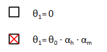
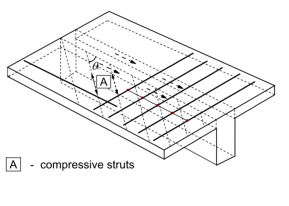
Type calculation / input of angle of compression strut
| Description |
Type calculation of angle of between of compression strut and member axis for shear check. - Auto - automatic calculation of minimum angle based on condition VEd ≤ VRd.max - User(angle) - the value is inputted by the user as angle - User(cotangent) - the value is inputted by the user as cotangent of the value |
| Default | Combo box; default = User(angle) |
|
Code |
6.2.3 |
| Level | Standard |
|
Figure |

|
| Member | All |
Angle of compression strut
| Description |
Angle between of compression strut and member axis for shear check; editable only if type of calculation of compression strut angle is User (angle) |
| Default | Edit box; θ = 40 ° |
|
Code |
6.2.3 |
| Level | Standard |
|
Figure |
|
| Member | All |
Cotangent angel of compression strut
| Description |
Cotangent angle between of compression strut and member axis for shear check; editable only if type of calculation of compression strut angle is User (cotangent) |
| Default | Edit box; cot(θ) =1,2 |
|
Code |
6.2.3 |
| Level | Standard |
|
Figure |
|
| Member | All |
Consider effect of axial force in non-prestressed shear check
| Description |
Checkbox if the effect of axial forces is taken into account or not. If it is considered then axial forces are included in the calculation of αcw coefficient which is used in calculation of VRd,max, otherwise αcw =1,0. |
| Default | Check box; default = False |
|
Code |
6.2.2(1) |
| Level | Advanced |
|
Figure |
- |
| Member | All |
Shear between web and flange
Type calculation / input of angle of compression strut
| Description |
Input type for angle between compression strut and member axis for longitudinal shear check. - User(angle) - the value is inputted by the user as angle - User(cotangent) - the value is inputted by the user as cotangent of the value |
| Default | Combo box, User (angle) / User (cotangent); default User (angle) |
|
Code |
6.2.4(4) |
| Level | Advanced |
|
Figure |
|
| Member | Beam, Beam slab, Rib |
Angle of compression strut
| Description |
Angle between compression strut and member axis for longitudinal shear check; editable only if type of calculation of compression strut angle is User (angle) |
| Default | Edit box, θf = 40 ° |
|
Code |
6.2.4(4) |
| Level | Advanced |
|
Figure |
|
| Member | Beam, Beam slab, Rib |
Cotangent angel of compression strut
| Description |
Cotangent of the angle between compression strut and member axis for longitudinal shear check; editable only if type of calculation of compression strut angle is User (cotangent) |
| Default | Edit box, cot(θf) = 1,2 |
|
Code |
6.2.4(4) |
| Level | Advanced |
|
Figure |
|
| Member | Beam, Beam slab, Rib |
Torsion
Equivalent thin walled cross-section
| Description |
Type of equivalent thin-walled cross-section used for calculation of cross-section capacity in torsion. Automatic - The program tries to create equivalent thin-walled cross-section from stirrup for torsion at first, and if this method is not successful, program uses method based on shape of cross-section. From stirrups from torsion - The program tries to create equivalent thin-walled cross-section around stirrup. From effective CSS - The program tries to create equivalent thin-walled cross-section from current cross-section by offsetting the value tef. From effective rectangular CSS - The program tries to create an equivalent rectangular concrete thin-walled cross-section the perimeter and area of which are the same as the perimeter and area of the original cross-section. For more details see "Stirrups for torsion" |
| Default | Combo box; default = Automatic |
|
Code |
6.3.1(3) |
| Level | Advanced |
|
Figure |
|
| Member | 1D (Beam, Beam slab, Column, Rib) |
Punching
Type of Beta factor
| Description |
Type of beta factor used in punching calculation Approximate - Values of beta factors are taken from figure 6.21N from EN 1992-1-1 Formula (DIN EN) - Values of beta factors are calculated according formula from DIN EN |
| Default | Combo box; Type β = Approximate |
|
Code |
6.4.3(3-6) |
| Level | Standard |
|
Figure |

|
| Member | Plate |
Control perimeter
Distance of control perimeter for ceiling plate
| Description |
The coefficient for determination of the distance of control perimeter of a ceiling plate from the column face (or from the previous perimeter if already exists). |
| Default | Edit box; coeff ku1,cel = 2,0 |
|
Code |
6.4.2(1) |
| Level | Advanced |
|
Figure |
|
| Member | Plate |
Distance of control perimeter for foundation plate
| Description |
The coefficient for determination of the distance of control perimeter of a foundation plate from the column face (or from the previous perimeter if already exists). |
| Default | Edit box; coeff ku1,found = 2,0 |
|
Code |
6.4.2(1) |
| Level | Advanced |
|
Figure |
|
| Member | Plate |
Distances for control perimeter are not editable in SCIA Engineer 19.0.
Distance from column face to consider openings
| Description |
The coefficient for determination of the distance from column face, where openings must be considered. |
| Default | Edit box; coeff kopen = 6,0 |
|
Code |
6.4.2(3) |
| Level | Advanced |
|
Figure |
|
| Member | Plate |
Stress limitations
Indirect load
| Description |
When the stress in reinforcement is caused by the indirect load (imposed deformation) then the stress should not exceed different maximal value |
| Default | Check box, default NO |
|
Code |
7.2(5) |
| Level | Advanced |
|
Figure |
|
| Member | All |
Stress limit in the reinforcement
Cracking forces
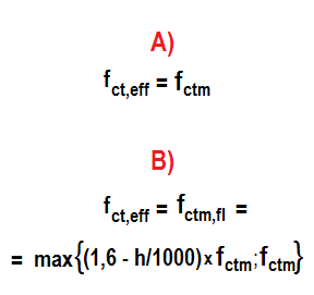
Type of strength for calculation of cracking forces
| Description |
Type of tensile strength of concrete used for calculation of cracking forces in SLS checks (stresses and deflections). It is possible to select between fctm (from Table 3.1) and fctm,fl (according Clause 3.1.8). |
| Default | Combo box; fct,eff = fctm |
|
Code |
7.1(2) |
| Level | Advanced |
|
Figure |
|
| Member | All |
Value of strength for calculation of cracking forces
| Description |
Value of strength of concrete used for calculation of cracking forces in SLS checks (stresses and deflections). It is possible to select between 0 MPa - first crack appears when tensile stress is reached in concrete cross-section fct,eff - first crack is appears when effective tensile strength is reached in cross-section |
| Default | Combo box; default = fct,eff |
|
Code |
7.1(2) |
| Level | Advanced |
|
Figure |
- |
| Member | All |
Crack width
Type of maximal crack width
| Description |
Possibility to automatically determined crack width according to exposure class combination and type of structure or to set user defied value of crack width |
| Default |
Combo box; default = AUTO - Auto - User - User different per surface |
|
Code |
7.3.1(5) |
| Level | Advanced |
|
Figure |
- |
| Member | All |
Deflection
Coefficient for increasing the amount of reinforcement
| Description |
Coefficient for increasing the amount of reinforcement for calculation of deflection (reduced stiffnesses). |
| Default | Edit box; default = 1,0 |
|
Code |
- |
| Level | Advanced |
|
Figure |
|
| Member | All |
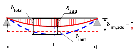
Maximal total displacement L/x; x =
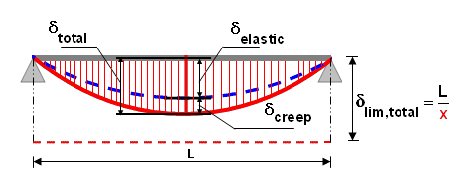
Maximal additional displacement L/x; x =
| Description |
Maximal additional (total - immediate) displacement allowed for 1D member expressed as span / depth ratio. |
| Default | Edit box; xadd = 500 |
|
Code |
7.4.1(5) |
| Level | Standard |
|
Figure |
|
| Member | 1D (Beam, Beam slab, Column, Rib) |
Maximal total deflection
| Description |
Maximal total (short-term + creep) deflection allowed for a 2D member input as an absolute value. |
| Default | Edit box; δlim,tot = 25 mm |
|
Code |
7.4.1(4) |
| Level | Standard |
|
Figure |

|
| Member | 2D (Plate, Wall, Shell(Plate), Shell(Wall), Deep beam) |
Maximal additional deflection
| Description |
Maximal additional (total - immediate) deflection allowed for a 2D member input as an absolute value. |
| Default | Edit box; δlim,add = 15 mm |
|
Code |
7.4.1(5) |
| Level | Standard |
|
Figure |
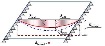
|
| Member | 2D (Plate, Wall, Shell(Plate), Shell(Wall), Deep beam) |
Type of variable load coefficient for the automatic generation of a combination for calculation of creep deflection
User-defined value of the variable load coefficient for the automatic generation of a combination for calculation of creep deflection
| Description |
User-defined value of the variable load coefficient for the automatic generation of a combination for calculation of creep deflection. The variable load used in the combination is multiplied by a user-defined value. This value is visible only if User input is selected in previous combo box. |
| Default | Edit box; default = 0,30 |
|
Code |
- |
| Level | Advanced |
|
Figure |
- |
| Member | All |
Detailing provisions
Beam (Rib)
Longitudinal
Check min. bar distance
| Description |
Setting if minimal clear bar distance of longitudinal reinforcement for beam is checked or not. |
| Default | Check box; default = True |
|
Code |
8.2(2) |
| Level | Standard |
|
Figure |
|
| Member | Beam, Rib |
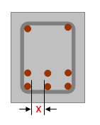
Minimal bar distance
| Description |
Additional limit for minimal clear bar distance of longitudinal reinforcement for beam. |
| Default | Edit box; slb,min = 20 mm; this item is visible only if check box above is set True |
|
Code |
8.2(2) |
| Level | Standard |
|
Figure |
|
| Member | Beam, Rib |
Check max. bar distance
| Description |
Setting if maximal clear bar distance of longitudinal reinforcement for beam is checked or not. |
| Default | Check box; default = False |
|
Code |
- |
| Level | Standard |
|
Figure |
|
| Member | Beam, Rib |
Maximal bar distance
| Description |
Additional limit for maximal clear bar distance of longitudinal reinforcement for beam. |
| Default | Edit box; slb,max = 350 mm; this item is visible only if check box above is set True |
|
Code |
- |
| Level | Standard |
|
Figure |
|
| Member | Beam, Rib |
Check max. bar distance (torsion)
| Description |
Setting if maximal centre-to-centre bar distance of longitudinal reinforcement for beam based on torsion requirement is checked or not. This value is checked if torsional moment exists in cross-section only. |
| Default | Check box; default = True |
|
Code |
9.2.3(4) |
| Level | Standard |
|
Figure |

|
| Member | Beam, Rib |
Maximal bar distance (torsion)
| Description |
Maximal centre-to-centre bar distance of longitudinal reinforcement for beam based on torsion requirement. This value is checked if torsional moment exists in cross-section only. |
| Default | Edit box; slbt,max = 350 mm; this item is visible only if check box above is set True |
|
Code |
9.2.3(4) |
| Level | Standard |
|
Figure |
|
| Member | Beam, Rib |
Check min. reinforcement area
| Description |
Setting if minimal reinforcement area of longitudinal reinforcement for beam is checked or not. |
| Default | Check box; default = True |
|
Code |
9.2.1.1(1) |
| Level | Standard |
|
Figure |

|
| Member | Beam, Rib |
Check min. reinforcement area for secondary member
| Description |
Setting if minimal reinforcement area of longitudinal reinforcement for secondary beam is checked or not. |
| Default | Check box; default = True |
|
Code |
9.2.1.1(1) |
| Level | Standard |
|
Figure |
|
| Member | Beam, Rib |
Check max. reinforcement area
| Description |
Setting if maximal reinforcement area of longitudinal reinforcement for beam is checked or not. |
| Default | Check box; default = True |
|
Code |
9.2.1.1(3) |
| Level | Standard |
|
Figure |

|
| Member | Beam, Rib |
Stirrups
Check min. mandrel diameter
| Description |
Setting if minimal mandrel diameter of stirrups for beam is checked or not. |
| Default | Check box; default = False |
|
Code |
8.3(2) |
| Level | Standard |
|
Figure |
|
| Member | Beam, Rib |
Check max. longitudinal spacing (shear)
| Description |
Setting if maximal longitudinal spacing of stirrups based on shear requirements is checked or not. |
| Default | Check box; default = True |
|
Code |
9.2.2(6) |
| Level | Standard |
|
Figure |
|
| Member | Beam, Rib |

Check max. longitudinal spacing (torsion)
| Description |
Setting if maximal longitudinal spacing of stirrups based on torsion requirements is checked or not. |
| Default | Check box; default = True |
|
Code |
9.2.3(3) |
| Level | Standard |
|
Figure |
|
| Member | Beam, Rib |
Check max. transverse spacing (shear)
| Description |
Setting if maximal transverse spacing of stirrups based on shear requirements is checked or not. |
| Default | Check box; default = True |
|
Code |
9.2.2(8) |
| Level | Standard |
|
Figure |
|
| Member | Beam, Rib |

Check min. percentage of stirrups
| Description |
Setting if minimal percentage of stirrups for beam is checked or not. |
| Default | Check box; default = True |
|
Code |
9.2.2(5) |
| Level | Standard |
|
Figure |
|
| Member | Beam, Rib |

Check max. percentage of stirrups
| Description |
Setting if maximal percentage of stirrups for beam is checked or not. |
| Default | Check box; default = True |
|
Code |
6.2.3(3) |
| Level | Standard |
|
Figure |
|
| Member | Beam, Rib |

Beam Slab
Longitudinal
Check min. bar distance
| Description |
Setting if minimal clear bar distance of longitudinal reinforcement for beam slab is checked or not. |
| Default | Check box; default = True |
|
Code |
8.2(2) |
| Level | Standard |
|
Figure |
|
| Member | Beam slab |
Minimal bar distance
| Description |
Additional limit for minimal clear bar distance of longitudinal reinforcement for beam slab |
| Default | Edit box; slbs,min = 20 mm; this item is visible only if check box above is set True |
|
Code |
8.2(2) |
| Level | Standard |
|
Figure |
|
| Member | Beam slab |
Check max. bar distance
| Description |
Setting if maximal bar distance of longitudinal reinforcement for beam slab is checked or not. |
| Default | Check box; default = True |
|
Code |
9.3.1.1(3) |
| Level | Standard |
|
Figure |

|
| Member | Beam slab |
Check min. reinforcement area
| Description |
Setting if minimal reinforcement area of longitudinal reinforcement for beam slab is checked or not. |
| Default | Check box; default = True |
|
Code |
9.3.1.1(1) |
| Level | Standard |
|
Figure |
|
| Member | Beam slab |
Check max. reinforcement area
| Description |
Setting if maximal reinforcement area of longitudinal reinforcement for beam slab is checked or not. |
| Default | Check box; default = True |
|
Code |
9.3.1.1(1) |
| Level | Standard |
|
Figure |
|
| Member | Beam slab |
Column
Longitudinal
Check min. bar distance
| Description |
Setting if minimal clear bar distance of longitudinal reinforcement for column is checked or not. |
| Default | Check box; default = True |
|
Code |
8.2(2) |
| Level | Standard |
|
Figure |

|
| Member | Column |
Minimal bar distance
| Description |
Additional limit for minimal clear bar distance of longitudinal reinforcement for column. |
| Default | Edit box; slc,min = 20 mm; this item is visible only if check box above is set True |
|
Code |
8.2(2) |
| Level | Standard |
|
Figure |
|
| Member | Column |
Check max. bar distance
| Description |
Setting if maximal clear bar distance of longitudinal reinforcement for column is checked or not. |
| Default | Check box; default = False |
|
Code |
- |
| Level | Standard |
|
Figure |
|
| Member | Column |
Maximal bar distance
| Description |
Additional limit for maximal clear bar distance of longitudinal reinforcement for column |
| Default | Edit box slc,max = 350 mm; this item is visible only if check box above is set True |
|
Code |
- |
| Level | Standard |
|
Figure |
|
| Member | Column |
Check max. bar distance (torsion)
| Description |
Setting if maximal centre-to-centre bar distance of longitudinal reinforcement for column based on torsion requirement is checked or not. This value is checked if torsional moment exists in cross-section only. |
| Default | Check box; default = True |
|
Code |
9.2.3(4) |
| Level | Standard |
|
Figure |

|
| Member | Column |
Maximal bar distance (torsion)
| Description |
Maximal centre-to-centre bar distance of longitudinal reinforcement for column based on torsion requirement. This value is checked if torsional moment exists in cross-section only. |
| Default | Edit box; slct,max = 350 mm; this item is visible only if check box above is set True |
|
Code |
9.2.3(4) |
| Level | Standard |
|
Figure |
|
| Member | Column |
Check min. reinforcement area
| Description |
Setting if minimal reinforcement area of longitudinal reinforcement for column is checked or not. |
| Default | Check box; default = True |
|
Code |
9.5.2(2) |
| Level | Standard |
|
Figure |
|
| Member | Column |
Check max. reinforcement area
| Description |
Setting if maximal reinforcement area of longitudinal reinforcement for column is checked or not. |
| Default | Check box; default = True |
|
Code |
9.5.2(3) |
| Level | Standard |
|
Figure |
|
| Member | Column |
Check min. bar diameter
| Description |
Setting if minimal bar diameter of longitudinal reinforcement for column is checked or not. |
| Default | Check box; default = True |
|
Code |
9.5.2(1) |
| Level | Standard |
|
Figure |

|
| Member | Column |
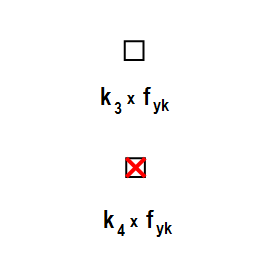
Check min. number of bars
| Description |
Setting if minimal number of bars in columns is checked or not. Option whether the program check: (i) minimal number of bars in circular columns and (ii) presence of at least one bar at each edge of a polygonal-shaped cross-section. |
| Default | Check box; default = True |
|
Code |
9.5.2(4) |
| Level | Standard |
|
Figure |

|
| Member | Column |
Min. number of bars in circular column
| Description |
Minimal number of bars in circular column. |
| Default | Edit box; nlc,min = 4 bars; this item is visible only if check box above is set True |
|
Code |
9.5.2(4) |
| Level | Standard |
|
Figure |

|
| Member | Column |
Transverse
Check max. percentage of stirrups
| Description |
Setting if maximal percentage of stirrups for beam is checked or not. |
| Default | Check box; default = True |
|
Code |
6.2.3(3) |
| Level | Standard |
|
Figure |
|
| Member | Column |
Check min. mandrel diameter
| Description |
Setting if minimal mandrel diameter of stirrups for column is checked or not |
| Default | Check box; default = True |
|
Code |
8.3(2) |
| Level | Standard |
|
Figure |
|
| Member | Column |
Check max. longitudinal spacing
| Description |
Setting if maximal longitudinal spacing of stirrups is checked or not. |
| Default | Check box; default = True |
|
Code |
9.5.3(3) |
| Level | Standard |
|
Figure |
|
| Member | Column |

Check min. bar diameter
| Description |
Setting if minimal diameter of longitudinal bar in column is checked or not. |
| Default | Check box; default = True |
|
Code |
9.5.3(1) |
| Level | Standard |
|
Figure |

|
| Member | Column |
Min bar diameter
| Description |
User defined minimal diameter of longitudinal bar in column. |
| Default | Edit box; dsc,min = 6 mm; this item is visible only if check box above is set True |
|
Code |
9.5.3(1) |
| Level | Standard |
|
Figure |
|
| Member | Column |
Min bar diameter
| Description |
User defined minimal diameter of longitudinal bar in column as multiplication factor of maximal diameter of longitudinal reinforcement. |
| Default | Edit box; xdsc = 25 %; this item is visible only if check box above is set True |
|
Code |
9.5.3(1) |
| Level | Standard |
|
Figure |
|
| Member | Column |
Plates, Shell (plate)
Longitudinal
Check min. ratio of principal reinforcement

Type of the minimum tension principal reinforcement for the upper surface
| Description |
Selection of the type of minimum tension reinforcement for each reinforcement layer at the upper surface of the plate. Auto - A) Automatic calculation of minimum tension reinforcement: The minimum reinforcement is evaluated with equation 9.1N. User value - B) Minimum tension reinforcement: The minimum tension reinforcement is calculated as a percentage of the area of concrete. |
| Default | Combo box; default = Auto; this item is visible only if check box above is set True |
|
Code |
- |
| Level | Standard |
|
Figure |

|
| Member | Plate, Shell(Plate) |
Minimum tension principal reinforcement for the upper surface [%]
| Description |
The minimum tension reinforcement of plate is calculated as a percentage of the area of concrete. |
| Default | Edit box; default = 0,2 %; this item is visible only if check box above is set True and combo box above is set User value |
|
Code |
- |
| Level | Standard |
|
Figure |

|
| Member | Plate, Shell(Plate) |
Type of the minimum tension principal reinforcement for the lower surface
| Description |
Selection of the type of minimum tension reinforcement for each reinforcement layer at the lower surface of the plate. Auto - A) Automatic calculation of minimum tension reinforcement: The minimum reinforcement is evaluated with equation 9.1N. User value - B) Minimum tension reinforcement: The minimum tension reinforcement is calculated as a percentage of the area of concrete. |
| Default | Combo box; default = Auto; this item is visible only if check box above is set True |
|
Code |
- |
| Level | Standard |
|
Figure |
|
| Member | Plate, Shell(Plate) |
The minimum tension principal reinforcement for the lower surface [%]
| Description |
The minimum tension reinforcement of plate is calculated as a percentage of the area of concrete. |
| Default | Edit box; default = 0,2 %; this item is visible only if check box above is set True and combo box above is set User value |
|
Code |
- |
| Level | Standard |
|
Figure |
|
| Member | Plate, Shell(Plate) |
Apply min. reinforcement ratio requirement
Check max. ratio of principal reinforcement
| Description |
Setting if maximal ratio of principal longitudinal reinforcement for plate and shell(plate) is checked or not. |
| Default | Check box; default = True |
|
Code |
9.3.1.1(1) |
| Level | Standard |
|
Figure |

|
| Member | Plate, Shell(Plate) |
Check min. transverse ratio of secondary reinforcement
| Description |
Setting if minimal transverse ratio of secondary longitudinal reinforcement for plate and shell(plate) is checked or not. |
| Default | Check box; default = True |
|
Code |
9.3.1.1(2) |
| Level | Standard |
|
Figure |
- |
| Member | Plate, Shell(Plate) |
Min. transverse ratio of secondary reinforcement
| Description |
Minimal value of transverse ratio of secondary longitudinal reinforcement for plate and shell(plate). |
| Default | Edit box; ρl,min,sec = 20 %; this item is visible only if check box above is set True |
|
Code |
9.3.1.1(2) |
| Level | Standard |
|
Figure |
- |
| Member | Plate, Shell(Plate) |
Check min. bar distance
| Description |
Setting if minimal bar distance of longitudinal reinforcement for plate and shell(plate) is checked or not. |
| Default | Check box; default = True |
|
Code |
8.2(2) |
| Level | Standard |
|
Figure |
- |
| Member | Plate, Shell(Plate) |
Minimal bar distance
| Description |
Additional limit for minimal bar distance of longitudinal reinforcement for plate and shell(plate). |
| Default | Edit box; slp,min = 20 mm; this item is visible only if check box above is set True |
|
Code |
8.2(2) |
| Level | Standard |
|
Figure |
- |
| Member | Plate, Shell(Plate) |
Check max. spacing of principal longitudinal reinforcement
| Description |
Setting if maximal spacing of principal longitudinal reinforcement for plate and shell(plate) is checked or not. |
| Default | Check box; default = True |
|
Code |
9.3.1.1(3) |
| Level | Standard |
|
Figure |

|
| Member | Plate, Shell(Plate) |
Check max. spacing of secondary longitudinal reinforcement
| Description |
Setting if maximal spacing of secondary longitudinal reinforcement for plate and shell(plate) is checked or not. |
| Default | Check box; default = True |
|
Code |
9.3.1.1(3) |
| Level | Standard |
|
Figure |

|
| Member | Plate, Shell(Plate) |
Shear
Check min. ratio of shear reinforcement
| Description |
Setting, if minimal ratio of shear reinforcement for plate and shell(plate) is checked or not. The minimal ratio of shear reinforcement is editable in Manager for national annexes. |
| Default | Check box; default = True |
|
Code |
9.3.2(2) |
| Level | Standard |
|
Figure |
- |
| Member | Plate, Shell(Plate) |
Check min. thickness of member with shear reinforcement
| Description |
Setting, if minimal thickness of member with shear reinforcement for plate and shell(plate) is checked or not. If this check is ON, then for thickness of slab lesser than minimal design of shear reinforcement finished with some warning. |
| Default | Check box; default = True |
|
Code |
9.3.2(1) |
| Level | Standard |
|
Figure |
- |
| Member | Plate, Shell(Plate) |
Min. thickness of member with shear reinforcement
| Description |
Minimal thickness of member with shear reinforcement for plate and shell(plate). |
| Default | Edit box; hmin = 200 mm; this item is visible only if check box above is set True |
|
Code |
9.3.2(1) |
| Level | Standard |
|
Figure |
- |
| Member | Plate, Shell(Plate) |
Check max. spacing of shear links
| Description |
Setting, if maximal spacing of shear link for plate and shell(plate) is checked or not. |
| Default | Check box; default = True |
|
Code |
9.3.2(4) |
| Level | Standard |
|
Figure |
- |
| Member | Plate, Shell(Plate) |
Max. spacing of shear links
| Description |
Coefficient for maximal spacing of shear links for plate and shell(plate). smax,p,s = Coeffsmax.p.s ∙ d ∙ (1 + cotg(α)) |
| Default | Edit box; Coeffsmax.p.s = 0,8; this item is visible only if check box above is set True |
|
Code |
9.3.2(4) |
| Level | Standard |
|
Figure |
- |
| Member | Plate, Shell(Plate) |
Wall, Shell(wall)
Longitudinal
Check min. ratio of vertical reinforcement
| Description |
Setting if minimal ratio of vertical longitudinal reinforcement for wall and shell(wall) is checked or not. |
| Default | Check box; default = True |
|
Code |
9.6.2(1) |
| Level | Standard |
|
Figure |
- |
| Member | Wall, Shell(Wall) |
Check max. ratio of vertical reinforcement
| Description |
Setting if maximal ratio of vertical longitudinal reinforcement for wall and shell(wall) is checked or not. |
| Default | Check box; default = True |
|
Code |
9.6.2(1) |
| Level | Standard |
|
Figure |
- |
| Member | Wall, Shell(Wall) |
Check maximal spacing of vertical reinforcement
| Description |
Setting if maximal spacing of vertical longitudinal reinforcement for wall and shell(wall) is checked or not. |
| Default | Check box; default = True |
|
Code |
9.6.2(3) |
| Level | Standard |
|
Figure |
- |
| Member | Wall, Shell(Wall) |
Max. spacing of vertical reinforcement
| Description |
Maximal spacing of vertical longitudinal reinforcement for wall and shell(wall) as multiplicand of wall thickness. |
| Default | Edit box; coef smax,v = 3; this item is visible only if check box above is set True |
|
Code |
9.6.2(3) |
| Level | Standard |
|
Figure |
- |
| Member | Wall, Shell(Wall) |
Max. spacing of vertical reinforcement
| Description |
Maximal spacing of vertical longitudinal reinforcement for wall and shell(wall). |
| Default | Edit box; smax,v = 400 mm; this item is visible only if check box above is set True |
|
Code |
9.6.2(3) |
| Level | Standard |
|
Figure |
- |
| Member | Wall, Shell(Wall) |
Check min. ratio of horizontal reinforcement
| Description |
Setting if minimal ratio of horizontal longitudinal reinforcement for wall and shell(wall) is checked or not. |
| Default | Check box; default = True |
|
Code |
9.6.3(1) |
| Level | Standard |
|
Figure |
- |
| Member | Wall, Shell(Wall) |
Check max. spacing of horizontal reinforcement
| Description |
Setting if maximal spacing of horizontal longitudinal reinforcement for wall and shell(wall) is checked or not. |
| Default | Check box; default = True |
|
Code |
9.6.3(2) |
| Level | Standard |
|
Figure |
- |
| Member | Wall, Shell(Wall) |
Max. spacing of horizontal reinforcement
| Description |
Maximal spacing of horizontal longitudinal reinforcement for wall and shell(wall). |
| Default | Edit box; smax,h = 400 mm; this item is visible only if check box above is set True |
|
Code |
9.6.3(2) |
| Level | Standard |
|
Figure |
- |
| Member | Wall, Shell(Wall) |
Check min. bar distance
| Description |
Setting if minimal bar distance of longitudinal reinforcement for wall and shell(wall) is checked or not. |
| Default | Check box; default = True |
|
Code |
8.2(2) |
| Level | Standard |
|
Figure |
- |
| Member | Wall, Shell(Wall) |
Minimal bar distance
| Description |
Additional limit for minimal bar distance of longitudinal reinforcement for wall and shell(wall). |
| Default | Edit box; slw,min = 20 mm; this item is visible only if check box above is set True |
|
Code |
8.2(2) |
| Level | Standard |
|
Figure |
- |
| Member | Wall, Shell(Wall) |
Transverse
Check max. spacing of shear links
| Description |
Setting, if maximal spacing of shear link for wall and shell(wall) is checked or not. The maximal spacing of shear links is editable in Manager for national annexes. |
| Default | Check box; default = True |
|
Code |
9.6.4(1) |
| Level | Standard |
|
Figure |
- |
| Member | Wall, Shell(Wall) |
Check min. number of shear links
| Description |
Setting, if minimal number of shear link for wall and shell(wall) is checked or not. |
| Default | Check box; default = True |
|
Code |
9.6.4(2) |
| Level | Standard |
|
Figure |
- |
| Member | Wall, Shell(Wall) |
Min. number of shear links
| Description |
Minimal number of shear links per square meter for wall and shell(wall). |
| Default | Edit box; nlinks.w = 4; this item is visible only if check box above is set True |
|
Code |
9.6.4(2) |
| Level | Standard |
|
Figure |
- |
| Member | Wall, Shell(Wall) |
Deep beam
Longitudinal
Check min. ratio of reinforcement
| Description |
Setting if minimal ratio of longitudinal reinforcement for deep beam is checked or not. |
| Default | Check box; default = True |
|
Code |
9.7(1) |
| Level | Standard |
|
Figure |
- |
| Member | Deep beam |
Check max. spacing of reinforcement
| Description |
Setting if maximal spacing of longitudinal reinforcement for deep beam is checked or not. |
| Default | Check box; default = True |
|
Code |
9.7(2) |
| Level | Standard |
|
Figure |
- |
| Member | Deep beam |
Max. spacing of reinforcement
| Description |
The maximal spacing of vertical longitudinal reinforcement for a deep beam as multiplication of deep beam thickness |
| Default | Edit box; coef smax,db = 2; this item is visible only if check box above is set True |
|
Code |
9.7(2) |
| Level | Standard |
|
Figure |
- |
| Member | Deep beam |
Max. spacing of reinforcement
| Description |
The maximal spacing of vertical longitudinal reinforcement for a deep beam. |
| Default | Edit box; smax,v = 300 mm; this item is visible only if check box above is set True |
|
Code |
9.7(2) |
| Level | Standard |
|
Figure |
- |
| Member | Deep beam |
Check min. bar distance
| Description |
Setting if minimal bar distance of longitudinal reinforcement for deep beam is checked or not. |
| Default | Check box; default = True |
|
Code |
8.2(2) |
| Level | Standard |
|
Figure |
- |
| Member | Deep beam |
Minimal bar distance
| Description |
Additional limit for minimal bar distance of longitudinal reinforcement for wall and shell(wall). |
| Default | Edit box; sldb,min = 20 mm; this item is visible only if check box above is set True |
|
Code |
8.2(2) |
| Level | Standard |
|
Figure |
- |
| Member | Deep beam |
Punching
Check min. shear reinforcement
| Description |
Setting if the minimum reinforcement area of a shear link is checked or not. |
| Default | Check box; default = True |
|
Code |
9.4.3(2) |
| Level | Standard |
|
Figure |
- |
| Member | Plate |
Check distance of the first perimeter of shear links
| Description |
Setting if the distance between the face of a column and the nearest shear reinforcement is checked or not. |
| Default | Check box; default = True |
|
Code |
9.4.3(1,4) |
| Level | Standard |
|
Figure |
|
| Member | Plate |
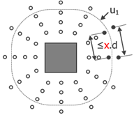
Min. distance from column face
| Description |
The coefficient for determination of the minimum allowed distance of the first perimeter of shear links from a column face. |
| Default | Edit box; coeff s0,min = 0,3; this item is visible only if check box above is set True |
|
Code |
9.4.3(1) |
| Level | Standard |
|
Figure |
|
| Member | Plate |
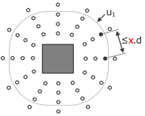
Max. distance from column face
| Description |
The coefficient for determination of the maximum allowed distance of the first perimeter of shear links from a column face. |
| Default | Edit box; coeff s0,max = 0,5; this item is visible only if check box above is set True |
|
Code |
9.4.3(4) |
| Level | Standard |
|
Figure |
|
| Member | Plate |
Check max. radial spacing of shear links
| Description |
Setting if the radial spacing between perimeters of shear links around a column is checked or not. |
| Default | Check box; default = True |
|
Code |
9.4.3(1) |
| Level | Standard |
|
Figure |
|
| Member | Plate |
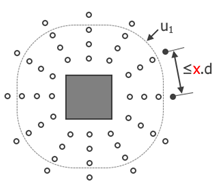
Max. spacing of shear links
| Description |
The coefficient for determination of the maximum allowed radial spacing between shear links around a column. |
| Default | Edit box; coeff sr,max = 0,75; this item is visible only if check box above is set True |
|
Code |
9.4.3(1) |
| Level | Standard |
|
Figure |
|
| Member | Plate |
Check max. tangential spacing of shear links
| Description |
Setting if the tangential spacing between perimeters of shear links around a column (within or outside basic control perimeter) is checked or not. |
| Default | Check box; default = True |
|
Code |
9.4.3(1) |
| Level | Standard |
|
Figure |
|
| Member | Plate |
Max. tangential spacing within the first control perimeter
| Description |
The coefficient for determination of the maximum allowed tangential spacing between shear links around a column within the basic control perimeter. |
| Default | Edit box; coeff st,max,u1 = 1,5; this item is visible only if check box above is set True |
|
Code |
9.4.3(1) |
| Level | Standard |
|
Figure |
|
| Member | Plate |
Max. tangential spacing outside the first control perimeter
| Description |
The coefficient for determination of the maximum allowed tangential spacing between shear links around a column outside the basic control perimeter. |
| Default | Edit box; coeff st,max,out = 2,0; this item is visible only if check box above is set True |
|
Code |
9.4.3(1) |
| Level | Standard |
|
Figure |
|
| Member | Plate |
Check minimum number of perimeters of shear links
| Description |
Setting if the minimum number of perimeters of shear links around a column is checked or not. |
| Default | Check box; default = True |
|
Code |
9.4.3(1) |
| Level | Standard |
|
Figure |
|
| Member | Plate |
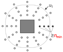
Min. number of perimeters of shear links
| Description |
The value of minimum number of perimeters of shear links around a column. |
| Default | Edit box; nper,min = 2; this item is visible only if check box above is set True |
|
Code |
9.4.3(1) |
| Level | Standard |
|
Figure |
|
| Member | Plate |