Introduction
Interaction diagram
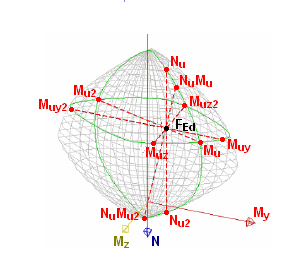
Interaction diagram is a graph illustrating the capacity of concrete member to resist a set of combinations of axial force and bending moments. Dependent on the load, the position of the neutral axis is changed and this leads to obtaining different values of compressive and tensile areas in concrete members. Therefore this concludes to a different capacity calculated from the strain distribution.
The Capacity - diagram calculates the extreme allowable interaction between the normal force N and bending moments My and Mz. In theory this diagram is a 3D-diagram, but SCIA Engineer allows the user to obtain horizontal and vertical sections. The axis of the diagram has an axis for the normal force N, the bending moment My and the bending moment Mz.
The effect of prestressing is introduced during preparation of interaction diagram. Then the verification is done just based on external load. The secondary forces from prestressing are added on the load side.
In the current version of SCIA Engineer the interaction diagram sections are not printed out.There are presented just resistances in each directions (NRd, MRdy, MRdz).
Check response (σ-ε)
The Capacity - response is based on the calculation of strain and stress in particular component (concrete fibre, reinforcement bar, tendon) and comparison with limited values with respect of EN 1992-1-1 requirements. Based on the internal forces, concrete cross-section and defined reinforcement by the user, SCIA Engineer is able to calculate the response of a member or a single cross-section. This method uses an iteration routine to calculate equilibrium based on the internal forces, the cross-section, material properties, reinforcement and prestressing layout. However, this method does not calculate extremes (capacities of cross-section) like the interaction diagram, but calculates the state of equilibrium for that section (response). The calculation also includes depth of compression zones (d), curvatures in each axis (εx, εy and εz), stresses, strains and forces in particular components. Generally, this iterative method works for the interaction of the normal force (N) with uni-axial or bi-axial bending moments (My + Mz). The method in the background uses per each component its initial stress which is caused by the all permanent part of the load .