Materials theoretical background
Characteristic basic residual values
The calculation of material characteristics is based on the document see[1] DAfStb Guideline "Steel fibre reinforced concrete".The calculation of characteristic values is dependent on fibre type and dosage. Each concrete class has recommended fibre types and dosages. Based on that the residual strengths values fR1,m to fR4,m are determined. These strengths are input for other calculation. Nevertheless the characteristic values will be presented in the material library as the first values for user (ffct0,L1; ffct0,L2; ffct0,u; ffct0,s). The input for calculation is list of measured values from the tests. This list is available for specific concrete class, fibre type and dosage (see the example below).
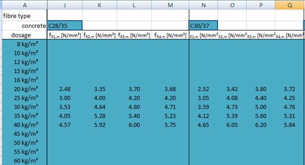
Note: There are implemented material characteristics fR1-4,m based on version 1.1.6 from Bekaert.
Then the following precondition is considered:
fR1,m = ffcflm,L1
fR4,m = ffcflm,L2
Next step is calculation of residual flexural strength from formula O.3 from German guideline (only limit value is used)
ffcflk,L1 = 0.51 ∙ ffcflm,L1
ffcflk,L2 = 0.51 ∙ ffcflm,L2
Then this strengths are used in formulas for characteristic values of residual tensile strength (see R.3.31-34) and will be visible in material library
ffcft0,L1 =ffcflk,L1 . βL1
ffcft0,L2 =ffcflk,L2 . βL2
ffct0,u =ffcflk,L2 . βu
ffct0,s =ffcflk,L2 . βs for L2/L1 ≤ 1,0
ffct0,s =ffcflk,L1 . βs for L2/L1 > 1,0
Beta factor calculation
Determination of beta factors (βL1 and βL2 is done based on figures P.1 and P.2 from see[1] DAfStb Guideline "Steel fibre reinforced concrete"
βL2 = 1 / 3 ∙ L2/L1 + 0,02
when
0,7 ≤ L2/L1 ≤ 1,0
or
βL2 = 0,18 ∙ L2/L1 + 0,17
when
1,0 ≤ L2/L1 ≤ 1,5
Determination of beta factors βs and βu
βu = 0,37; for the stress block
βs = 0,37; when using reinforcement
When ratio L2/L1 is mentioned in the text above it means ratio of fR4,m / fR1,m is used
Residual values
The second step of calculation material characteristic is calculation of residual values from characteristic ones. Member size and fibre orientation are another items affecting the calculation The simplification is done by taking into account values
| κfG |
member size effect; there will be one factor per material and for slab = 1,7 |
| κfF |
fibre orientation effect = 1,0 for bending and tensile loads = 0,5 for shear |
Both values will be possible to edit in material library per specific material. Additionally, there will be two values for κfF (general and for shear only) - see[1] DAfStb Guideline "Steel fibre reinforced concrete".
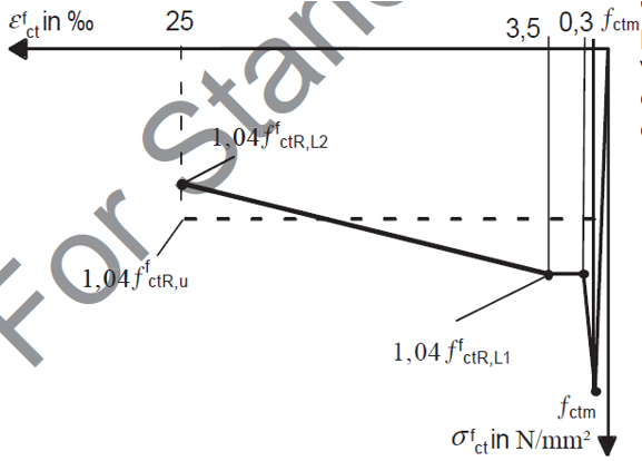
Then residual values of material characteristics are calculated using the following formulas (see R.3.36-39):
ffctR,L1 = κfF ∙ κfG ∙ ffct0,L1
ffctR,L2 = κfF ∙ κfG ∙ ffct0,L2
ffctR,u = κfF ∙ κfG ∙ ffct0,u
ffctR,s = κfF ∙ κfG ∙ ffct0,s
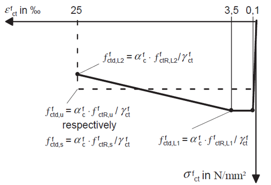
Design values
The third step of calculation material characteristic is calculation of design values from residual ones.
ffctd,L1 = αfc . ffctR,L1 / γfct
ffctd,L2 = αfc . ffctR,L2 / γfct
ffctd,u = αfc . ffctR,u / γfct
ffctd,s = αfc . ffctR,s / γfct
where
| αfc |
reduction factor which is aligned with the design concept of this document to allow for long-term effects on the residual tensile strength of steel fibre reinforced concrete (see[1] DAfStb Guideline "Steel fibre reinforced concrete") = 0,85 |
| γfct |
partial safety factor according to Table R.1 (see[1] DAfStb Guideline "Steel fibre reinforced concrete") = 1,25 |
Material diagrams
The material diagrams are completely different than standard concrete material diagrams. The effect of fibres are taken into account by tensile branch. Here just behaviour in tension is described
There are two types of material diagram used in analysis dependent on analysis type:
-
diagram for linear analysis and section design - this diagram is based on design values
- diagram for nonlinear analysis - this diagram is based on residual values