3D Wind-Load Generator - Canopy
The load generation for Canopies is done in accordance with EN 1991-1-4:2005 (E), chapter 7.3. This automatic generation of load is available for EC-EN (Eurocode).
A canopy roof is defined as the roof of a structure which does not have permanent walls, e.g. petrol station shelters, bus-stop shelters, and similar.
Wind data type - Canopy
Wind data type - Canopy needs to be selected in order to generate the load correctly for this type of structure.
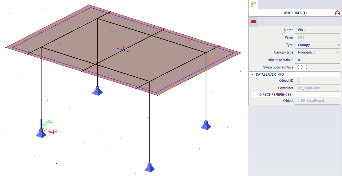
Three Canopy types are available: Flat, Monopitch and Duopitch (Monopitch as example in the figure above). According to modelled structure and the canopy slope, the user needs to set the corresponding one.
The "blockage ratio φ" is to define as a canopy property. Allowed values are in interval (0, 1). If a value outside this interval is input, a warning window with a message "input values must be in interval 0, 1" is shown. The blockage ratio modifies the applied load in dependence on airflow around the structure influenced e.g. by stored goods under the shelter, or other obstacles for the wind flow, as defined in the figure 7.15. from EN 1991-1-4:

Coefficient type
It is possible to choose from two coefficient types for canopies:
- "Net pressure Cp"
Example:
- "Overall force Cf"
Example:
This settings is available in: "Project data" - "Setup manager" for wind load - "Coefficient type":

Canopy zones
For nonorthogonal canopy shapes it is possible to choose from two options for direction of canopy zones:
- "Standard" - the direction of zones is according to the GCS
- "Parallel to edges" - the direction of the zones is parallel to the canopy edges
This settings is available in: "Project data" - "Setup manager" for wind load - "Canopy zones direction":

Example of "Standard":

Example of "Parallel to edges":

Generated loads
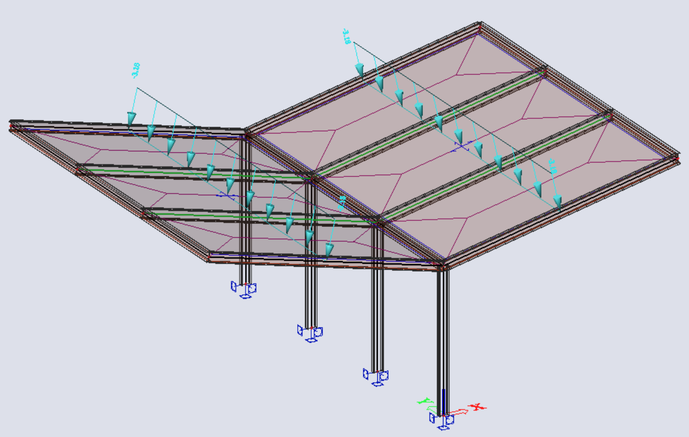
- For the "net pressure Cp" are the geometry of zones and used pressure coefficients determined in accordance with the table 7.6 and table 7.7. (EN 1991-1-4) for monopitch (and flat) canopies and duopitch canopies respectively.


Note: The C_p,net coefficient as defined in the EN tables (figures above) is in SCIA interpreted as the C_pe coefficient (coefficient of external air pressure). Coefficient of internal air pressure C_pi is for canopy always considered as 0. Hence, the net pressure applied on the structure w_net = q_p(z) * (C_pe - C_pi) is for canopy considered as w_net = q_p(z) * C_pe ; where q_p(z) is the peak pressure dependent on the height z. See the example for the monopitch canopy below.
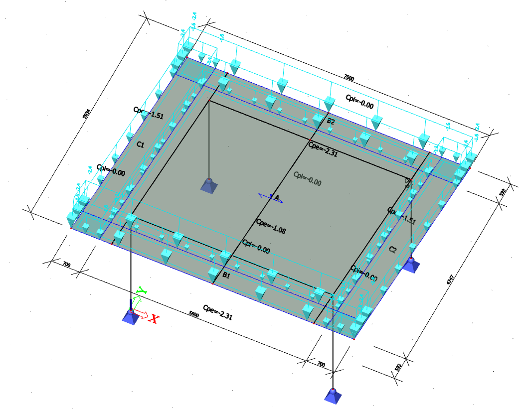
Example of the monopitch canopy - slope 8,53°, blockage ratio φ = 0%. Air pressure is being checked. By linear interpolation, expected values of C_pe for zones A, B and C are: 1.0824, 2.3118 and 1.5118 respectively:

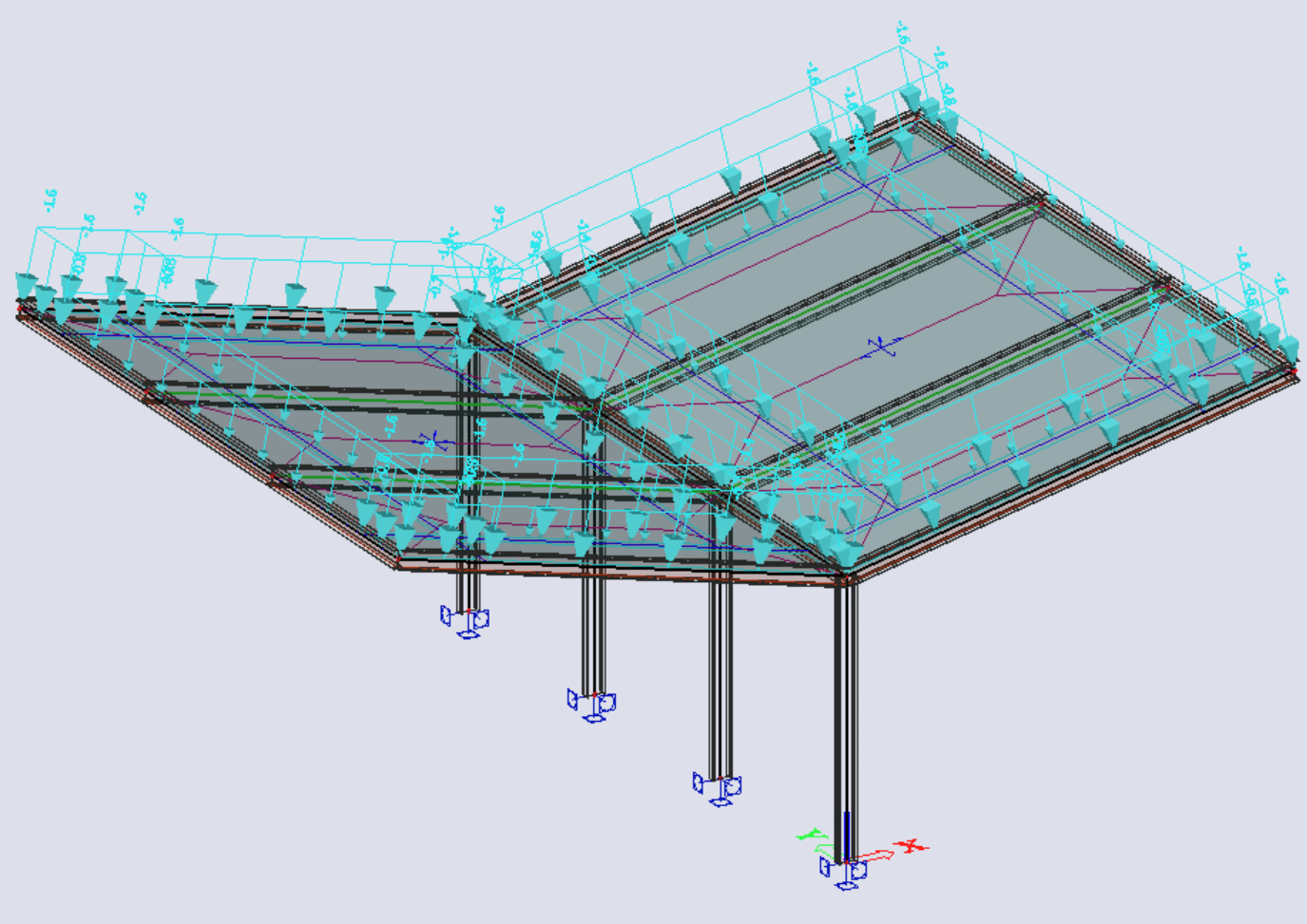
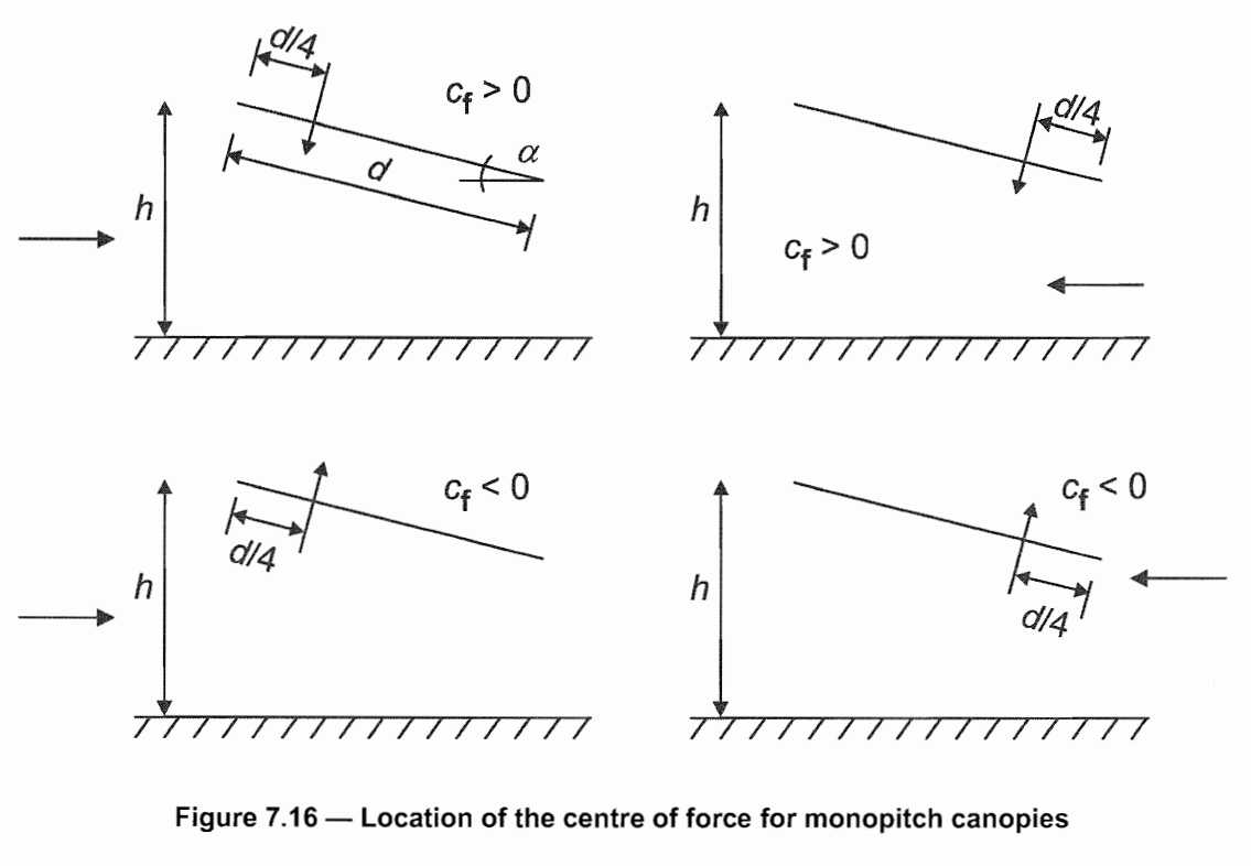
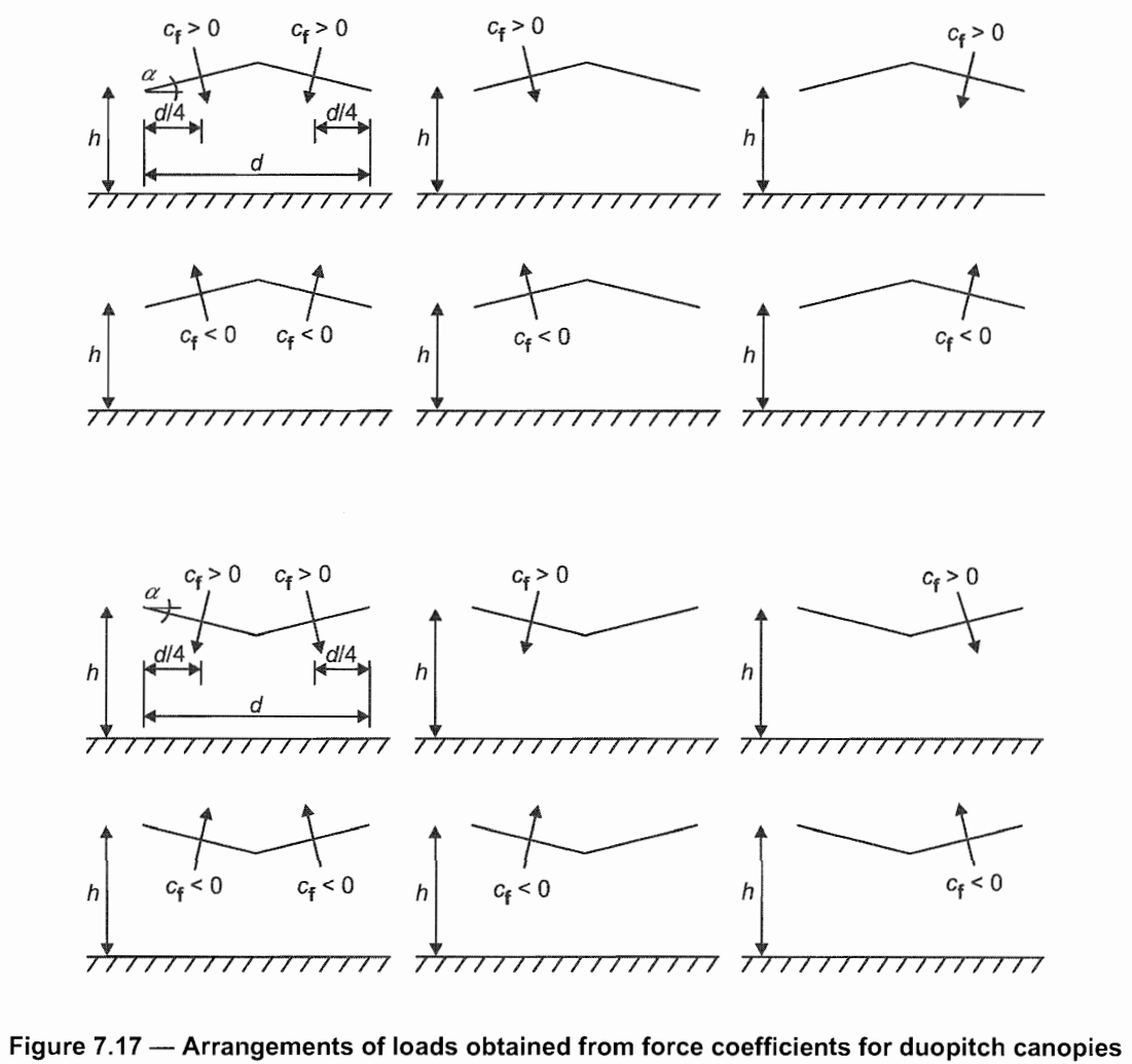
- For the "overall force Cf" are the used pressure coefficients also determined according to the table 7.6 and table 7.7. (EN 1991-1-4) listed above. The geometry of the line load is according to the Figure 7.16 and 7.17 (EN 1991-1-4):
Corner zone overlapping
The geometry of zones for the "net pressure Cp" according to the EN 1991-1-4 chapter 7.3 is following:

There is not exactly defined which zone should be considered in the corners. In Scia Engineer, there are separate zones created in the corners. For each load case are the zones B and C evaluated and for the corners is chosen the bigger value of Cp from these two zones.
