Adjusting
the view
SCIA Engineer offers a wide range of functions to adjust the required view. Using the NaviCube is the preferred method, however, some more advanced possibilities are also listed below.
Using the NaviCube
|
|
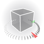
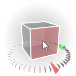
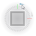
The NaviCube is located at the bottom right corner of the graphic window.
The cube itself shows a fictive object oriented according to the global coordinate system of the model. The ticked ring shows the orientation of a horizontal plane. The red and green marks indicate the global X and Y axes, respectively.
|
|
|
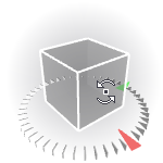
Tumble (rotate)
Click and hold the cube with the left mouse button, then move the mouse
|
|
|
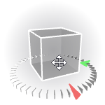
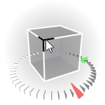
Pan (translate)
Click and hold the cube with the middle mouse button, then move the mouse
|
|
|
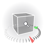
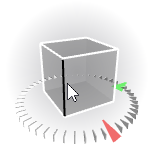
Zoom
Click and hold the cube with the right mouse button, then move the mouse up or down
|
|
|
To set the view in the direction of one of the global axes, click on the corresponding face of the cube
To set the view in the opposite direction, click again on the same face
|
|
|
To set a view facing a corner of the cube, click the corresponding corner |
|
|
To set a view facing an edge of the cube, click the corresponding edge |
|
|
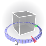
To rotate the view around the vertical axis, click and hold the ring at the bottom of the cube and move the mouse left or right |
|
|
In top view only, to rotate the view by 90° around the vertical axis, click on the arrows next to the ring |
|
|
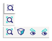
The viewbar next to the NaviCube offers additional view change features |
|
|
Zoom on the entire model
|
|
|
Zoom on the selection
|
|
|
Switches between isometric and perspective view |
|
|
Switches to the previous / next view point |
Mouse controlled adjustment of the view
In addition to the NaviCube, SCIA Engineer
offers also a set of fast-access functions for the view adjustment.
|
Zoom
in/out
|
- Use the mouse wheel
- Press [Ctrl]
and [Shift] keys simultaneously
and hold them down. Then press the right mouse button and hold
it down as well. Move the mouse up or down over the pad.
|
|
Rotate
|
- Press [Ctrl]
key and hold it down. Then press the right mouse button and hold
it down as well. Move the mouse over the pad in order to get the
required view direction.
|
|
Pan
|
- Press and hold the middle mouse button and move the mouse
- Press [Shift]
key and hold it down. Then press the right mouse button and hold
it down as well. Move the mouse over the pad in order to get the
required position of the structure on the screen.
|
|
Zoom
All
|
Double-click
the middle-button of your mouse to invoke function Zoom
All.
|
Rotation of view
The centre of rotation depends on initial conditions.
|
No
entity is selected
|
The centre of rotation is put into the point
that forms a centroid of an imaginary rectangular prism outscribed
around the existing model.
|
|
Some
entities are selected
|
The centre of rotation is put into the point
that forms a centroid of an imaginary rectangular prism outscribed
around the selected entities.
|
|
One
node is selected
|
The selected node is the centre of rotation.
|
|
Clipping
box is ON
|
The centre of rotation is put into the point
that forms a centroid of the current clipping box.
|
Menu functions for adjustment of the view
This mode of navigation is still available through the menu and, in some cases, the context menu. However it is deprecated and will ultimately be removed completely.
|
View >
ZOOM > Zoom +
|
Zooms in.
|
|
View >
ZOOM > Zoom -
|
Zoom out.
|
|
View >
ZOOM > Zoom Cut-out
|
Requires to define a cut-out for the zoom.
The cut-out is then magnified in order to fit into the whole area
of the graphical window.
Once the function is started the mouse cursor
changes. Position it to the upper left corner of the cut-out.
Press the left mouse button and hold it down. Drag the mouse to
place the cursor to the bottom right corner of the cut-out. Release
the button.
|
|
View >
ZOOM > Zoom All
|
Zoom in or out in order to fit the whole
structure into the whole area of the graphical window.
|
|
View >
ZOOM > Zoom All – Selection
|
Zoom in or out in order to fit the selected
entities into the whole area of the graphical window.
|