Making a selection
In order to make a selection, the program must be in the selection-enabled mode. This mode is the default mode of the program and only a limited number of functions changes this mode into a selection-disabled mode. The selection-enabled mode is identified by the mouse cursor that looks like a diagonally oriented arrow with a small square attached to the tip of the arrow. Once this cursor is on the screen, it is possible to make selections freely.
There are two basic ways to make a new selection: using the mouse or typing a command on the command line. In both ways it is a piece of cake.
In addition, a selection can also be made via filters. That means, that the user specifies a condition that should be fulfilled by all selected entities. For example, the user may specify the condition that the cross-section must be a rolled IPE 300. The filter-controlled selection then looks for and selects all 1D members with such a cross-section.
Making a selection by the mouse cursor
When using the mouse cursor, there are several selection modes:
How to activate the required selection mode
|
selection mode |
|
via main menu > Tools > Selections |
|
Single selection |
|
call function Select by mouse |
|
Intersection line |
|
call function Select by intersection |
|
Rectangular cutout |
|
call function Select by cutout |
|
Polygonal cutout |
|
call function Select by polygon |
|
Workplane |
|
call function Select by work plane |
|
Select all |
|
call function Select all |
| Deselect all | 
|
call function Deselect all |
|
Previous |
|
call function Previous selection |
|
Toggle single selection mode |
|
see paragraph Selection of entities with overlapping edges |
|
Toggle deselection mode |
|
see topic Removing the entities from selection |
|
Toggle visibility selection mode |
|
see paragraph Visibility selection mode |


Single selection
In order to make a selection, the user has to:
-
place the mouse cursor on the entity he/she wants to select,
-
click the left mouse button.
That is all that is necessary to make a selection by mouse. To add another entity, the user just puts the cursor on another entity and clicks the left mouse button.
Intersection line
When this mode is invoked, all entities that are intersected by a defined line are added into the selection. The line may be either a single straight line or a polygon consisting of straight lines.
The procedure to define a polygon
-
Position the mouse cursor to the place where the polygon should start.
-
Click the left mouse button.
-
Position the mouse cursor where the end point of the polygon line segment should be located.
-
Click the left mouse button.
-
Repeat the previous two steps as many times as required.
-
Close the polygon, ie. either
-
press [ESC] key, or
-
define the last point with the right mouse button.
-
Cutout
This mode enables the user to select all entities located inside a mouse defined cut-out. There are two different kinds of the cut-out. The first one serves for selection of entities located fully inside it. The other one can be used to select entities that are both fully inside and overlap the cut-out.
The procedure to define a cutout that selects inside-located entities only
-
Place the mouse cursor to the TOP LEFT corner of the rectangular cut-out.
-
Press the left mouse button and hold it down.
-
Drag the mouse to the BOTTOM RIGHT corner of the rectangular cut-out.
-
Release the button.
The procedure to define a cutout selecting both inside-located and overlapping entities
-
Place the mouse cursor to the TOP RIGHT corner of the rectangular cut-out.
-
Press the left mouse button and hold it down.
-
Drag the mouse to the BOTTOM LEFT corner of the rectangular cut-out.
-
Release the button.
Polygon
This mode is similar to the previous one. The difference is that the user draws an arbitrarily shaped closed polygon instead of a simple rectangle.
The procedure to define a polygonal cut-out
-
Position the mouse cursor to the place where the polygon should start.
-
Click the left mouse button.
-
Position the mouse cursor where the next vertex of the polygon should be located.
-
Click the left mouse button.
-
Repeat the previous two steps as many times as required.
-
Close the polygon:
-
either press [ESC] key, or
-
define the last point with the right mouse button.
-
Work plane
In this mode, the program automatically selects all entities located in the current workplane.
Select all
All displayed entities are automatically selected.
Selection of entities with overlapping edges
In a real-life model it is frequent situation that several entities (e.g. beams, walls) meet in one place (joint, corner). In that case it may be difficult to select the proper entity, because when you place the mouse cursor over the intersection of these entities, the program does not know, which one to select. To solve such situations, the program offers a special toggle: Single selection. This switch enables you to work in two modes:
First found
In this mode, the first entity found by the selection algorithm is selected (usually, it is the entity that was input first).
All found
In this mode, the program finds all entities under cursor and offers you a list of them so that you may decide yourself which one(s) should be selected.
Imagine a simple model of three walls.

If you place the cursor over the corner in which the three walls meet and click the left mouse button, the program opens a small dialogue with a list of found entities.
You may roll the mouse cursor over the list. The entity over which the cursor is just placed is highlighted in the graphical screen, so it is easy to find out which entity is which.

If you want to select a particular entity, just click on its name in the list. You may select as many entities as you want.

When you press the blue-mark button, the selection is confirmed.

Visibility selection mode
In the "normal" selection mode, you must select an edge of an entity in order to select it.
However, if the Visibility selection mode is activated, you may just put the mouse cursor anywhere on the displayed member and it can be selected. The only precondition is that Rendering display style is active.
The Single selection mode toggle is taken into account in the Visibility selection mode.
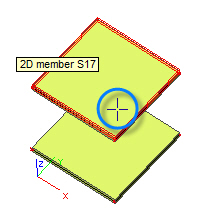
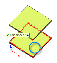
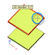
Examples (the little cross in the blue circle indicates the position of the mouse cursor):
A) Single selection mode toggle set to FIRST FOUND
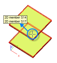
B) Single selection mode toggle set to ALL FOUND
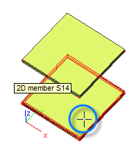
Please note that the cursor changes its shape when the program is in the visibility selection mode.
Filter-controlled selection
The filter-controlled selection is useful if the user wants to select all entities that meet a specific condition. This type of selection is described in the following chapter.
Making a selection from the command line
A selection can be also made (sometimes very effectively) from the program’s command line.
The procedure is similarly simple as the "mouse procedure". The user types a command on the command line and the selection is made.
Command syntax
SEL [switch] parameter [parameter2] [parameter3] [etc.]
Switch
|
switch |
meaning |
|
+ |
adds into selection |
|
- |
subtracts from the current selection |
Parameter
|
parameter |
example |
description |
|
entity name |
SEL BEAM23 |
selects entity named BEAM23 |
|
entity name with a wildcard |
SEL B* |
selects all entities whose name starts with letter B |
|
none |
SEL NONE |
clears the selection |
Examples
|
sel none |
clears the selection |
|
sel * |
selects all entities |
|
sel N1 |
selects entity N1 |
|
sel N1 B1 |
selects entities N1 and B1 |
|
sel + N* |
adds into the current selection entities whose name starts with N |
|
sel – B* |
removes from the current selection entities whose name starts with B |
Making a selection of a mesh node from the command line
To select a mesh node by its number, command SELMN can be used.
Procedure to select required mesh nodes
1. Type command SELMN in the SCIA Engineer command line and press Enter.
2. The selection function starts.
3. Type the number of the node to be selected and press Enter. The node is marked with an arrow.
4 . If required, repeat step 3.
5. Press Esc to end the command.
IMPORTANT: In order to see the arrow denoting the selected node(s) it is necessary to switch ON the appropriate flag in the View parameters settings Dialogue - Misc. > Calculation info > Display arrow on mesh elements.
Procedure to remove the highlighting arrow from selected mesh nodes
1. Select the arrow or the accompanying text with the mouse cursor.
2. Press key Delete on your keyboard OR use the Delete function from the pop-up menu OR use the Delete function from the Modify menu.