Tracking tools
Tracking point
The point is displayed by a light blue rectangle. The last inserted point is automatically switched to the tracking point. Other tracking points are user defined. It can be switched snapping point or tracking point placed anywhere by user.
There is no geometry (or add data) created when user creates the tracking point, it is only an assistant point. It helps to track another position.
There are two types of tracking points:
- The first with the crossed blue rectangle is the last inserted point in the project and it cannot be disabled. It is the default point for creating the next member.

- The second point is user defined. It can be disabled. User creates it from the snapping point or it is inserted as user defined tracking point anywhere in the project.


The tracking points are automatically deactivated when the actual command is finished or canceled.
The active tracking point is displayed by thicker rectangle. It is the tracking point from which the tracking ray is displayed.

The tracking points can be inputted more times to the project.
How to disable the tracking point - see the separate chapter.
Switched tracking point
The snapping point is displayed by moving the cursor over the point, it is displayed by the red rectangle. This point is switched to the tracking point by moving the cursor over the snapping point and holding the SHIFT key.
No clicking is needed.

The tracking points can be created on all types of snapping points.
The displaying of the snapping points depends on its settings.
User defined tracking point
The user defined tracking point can be inserted anywhere in the project . This point is created by holding the SHIFT key and clicking to its position.

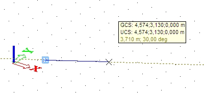
Tracking ray
This is the dot line which is displayed from the active tracking point.
The directions are according to the global coordinate and according to the user defined angles. When the tracking line corresponds to the coordinate direction, it has the same colour. If user defined angle is used, the tracking ray is displayed by the yellow colour.
The cursor is automatically snapped to the ray so it is easy to move on it.

Tracking line
This tool works with already inserted lines and polygons in the project (center line, edge, 3D line).
It is similar to the tracking ray. It doesn't display the dot line, but it marks geometry as a tracking line. The colour of the tracking line is light blue (the same colour as we have for the tracking point). The major difference is, that tracking ray doesn't have the begin and end node but the tracking line has it because it is limited by the used geometry.

Start point on tracking line
The start point on the tracking line is displayed as a blue circle. It is begin or end node of the line - it is controlled by the tracking settings.

Disable switched tracking point or tracking line
The tracking point (line) can be disabled by moving the cursor over the tracking point with holding SHIFT + CTRL key.
The original snapping point or line is displayed again.
Intersection point
The intersection of two tracking rays (or the tracking line and ray) is displayed by a small circle. This point is exact intersection and user can snap to it.
Between two tracking rays:
Between the tracking ray and tracking line: