How to use tracking mode to insert a new structure
Create a simple structure using tracking mode:
Building with 2 floors and one inclined wall on the second floor.

Introduction to basic tracking tools - point, line, intersection:
Tracking point - point which is a starting point for a tracking rays

Tracking line - geometry line or polyline which can be used in the same way as tracking ray

Tracking intersection - is a point where one ray cross the other ray

Start with a new empty project:
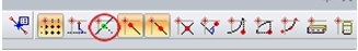
- Open a new empty project with concrete. Tracking is controlled by the button on the bottom of the 3D window. Switch it on.
- The tracking settings for is under “Dot grid and tracking settings".
- We need to set one angle of rays. Open dialogue “Dot grid and tracking settings” and use button – “Setup for tracking …”. We use the tracking ray with this angle for inserting inclined wall on the second floor.

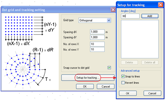
- Add a new angle 30°. Write the value to the row and use the button "Add". Check if the checkbox for “Snap to lines” is active.
Modeling
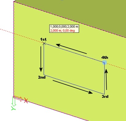
- Create the first level of our building on working plane. We will create 4 walls, 1 plate and some openings. Activate the dotgrid snapping to define the size by the simplest way.
- It is possible to snap to the dotgrid and also see the distance in the tooltip.

- The 1st wall starts in point 0,0,0. The length is 5m. The tracking tooltip shows the distance
.

- Create the 2nd wall from end point of the 1st wall. Length of the 2nd wall is 6m. See the next picture.

- We use a new type of intersection tracking point to create the 3rd wall. The length of the 3rd wall is 5m.
How to create the tracking intersection point:
- Insert 1st point of the 3rd wall.
- Move over the node in 0,0,0 and hold SHIFT. This node is automatically marked with theblue rectangle.
- This point now works as tracking point – it means that we can use rays from this point. Now we have two points with rays.
- Intersection point is on the intersection of those two rays. New intersection point is automatically marked with little circle.

- Insert a plate on walls. Create some openings in the walls.
- Use tracking rays during the creating openings. Sizes are defined by the dotgrid.
- The second floor is defined by 5 walls and we use ray under 30 ° angle to create the 3th wall as inclined wall.
- The 1st wall has the same size as wall under it.

- The 2nd wall has thethe same size as the wall under it. The 3rd wall is shorter – the length is only 4m.
- Create the 4th wall using the tracking ray under angle 30°. Start from the end point of the 3rd wall and use the user-defined tracking point on the starting point of the 1st wall. The intersection point is created by ray under 30° and the ray from the new tracking point on the left corner. See the picture.

- Create some opening on the second floor.

Create a roof using user-defined length in the command line.
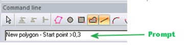
- We use command line (prompt) to define attic height.
- Start a command for inserting a new plate but don't create any point.
- Set a new user-defined tracking point on the top node.

- Move the cursor on the ray downwards to define the correct direction. Write 0,3 to the command line (just write 0,3 on keyboard, the value is automatically inputted to the command line) and press Enter. The first inserting point of the plate is created.

- Move the cursor on the ray from last point next corner – see the picture.

- Define the edge of the wall as a tracking curve. Move cursor over the edge and hold CRTL. Curve is automatically highlighted by the blue color.

- There is an tracking intersection point on the tracking curve and the tracking ray.
- Use the same approach for creating the whole roof – using tracking lines on edges and tracking rays from the last inserted points.

The final structure is in the project "final_track.esa".