Align
This function can do the same as the original Align function and has some new extra functionality. New options for displaying of alignment-results before you perform the action itself are available.
Show alignment info
if ON, Alignment Info dialog is shown. There are four tabs:
Conflicts
shows a list of all entities which are in a conflict with others.
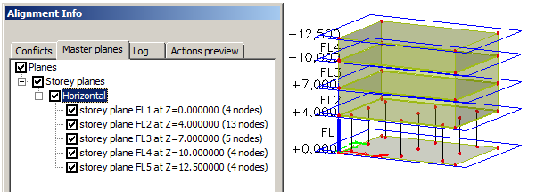
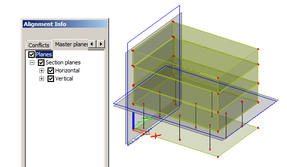
Master planes
shows a list of all mater planes which will be used for alignment. If you click any master plane or group of master planes you can see it displayed with a blue contour in the graphical window.
Log
shows various information, e.g. about limits, etc.
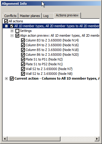
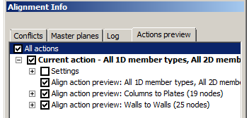
shows a list of all selected actions. If you click any action or group of actions you can see the results with a blue contour in the graphical window.
Live preview
if ON, you can see the results of selected options in the graphical window before you perform the function itself.
Master planes
UCS XY planes
if ON, entities are aligned to fit into XY planes of defined UCSs.
Storey planes
if ON, entities are aligned to fit into defined storey planes.
Section planes
if ON, entities are aligned to fit into defined section planes.
Line Grid planes
if ON, entities are aligned to fit into planes of defined line grids.
LCS planes (1D members)
if ON, entities are aligned to fit into XY or XZ planes of 1D members. This option hast to be ON if you want to use actions for 1D members.
Extend 1D member planes
LCS planes of 1D members are extended to infinity.
LCS planes (2D members)
if ON, entities are aligned to fit into XY plane of 2D members. This option has to be ON if you want to use actions for 2D members.
Extend 2D member planes
LCS planes of 2D members are extended to infinity.
Limits
Min. distance between parallel master planes [m]
defines the minimal distance of two parallel planes. If the distance of a node is smaller than this value, no new parallel plane is created in the node.
Min. angle between master planes [deg]
defines the minimal angle between master planes. If the angle between the existing plane and a master plane for a particular node is lower than this value, no new parallel plane is created in the node.
Correct angle of planes similar (within limit) to
GCS main planes
If ON, entities are aligned to fit into XY GCS parallel planes.
UCS XY planes
if ON, entities are aligned to fit into XY parallel planes of defined UCSs.
Actions (align nodes of)
This group of options specifies which structural type of members should be aligned with other structural type of member.
All 1D and 2D members to
All 1D member types
all 1D and 2D member are aligned to fit into LCS planes of 1D members.
All 2D member types
all 1D and 2D member are aligned to fit into LCS planes of 2D members.
Beams to
Columns
only all beams are aligned to fit into LCS planes of columns.
Walls
only all beams are aligned to fit into LCS planes of walls.
Plates
only all beams are aligned to fit into LCS planes of plates.
All 1D and 2D members
only all beams are aligned to fit into LCS planes of 1D or 2D member.
Columns to
Beams
only all columns are aligned to fit into LCS planes of beams.
Walls
only all columns are aligned to fit into LCS planes of walls.
Plates
only all columns are aligned to fit into LCS planes of plates.
All 1D and 2D members
only all columns are aligned to fit into LCS planes of 1D or 2D members.
Plates to
Plates
only all plates are aligned to fit into LCS planes of other plates.
Walls
only all plates are aligned to fit into LCS planes of walls.
All 1D and 2D members
only all plates are aligned to fit into LCS planes of 1D or 2D members.
Walls to
Beams
only all walls are aligned to fit into LCS planes of beams.
Walls
only all walls are aligned to fit into LCS planes of other walls.
All 1D and 2D members
only all walls are aligned to fit into LCS planes of 1D or 2D members.
Max. node-to-master plane distance [m]
defines maximal distance when a node is aligned into the master plane. If the distance is bigger the function is not performed.
Max. total displacement of node [m]
defines the maximal total displacement of a node when the node can be moved into a master plane. If the total displacement is bigger the node is not moved. This value must not be lower than the value specified above.
Display options
Highlight master planes
if ON, the contour representing the master plane is in bold.
Highlight nodes with plane
if ON, all nodes which are aligned to fit into a plane are displayed in bold in a colour which is set for the preview.
Note: Live Preview must be enabled for highlighting of nodes.
Preview shows master planes
if ON, master planes are displayed also for Live Preview.
Preview shows nodes
if ON, nodes which are aligned to fit into a plane are also displayed in Live Preview.
Preview colour
specifies the colour of Live Preview.
Advanced
Keep openings in their original position
If ON, all openings which do not have any node with the master slab in common remain in their original position, i.e. they are not aligned to the edge of member.
Keep original shape of the model (by eccentricities)
If ON, the structural model shape remain in the original position and only the analysis model is aligned.
Parameterize the structure by master planes
this option is available only if at least one coordinate of a structure node is defined by means of a parameter.
Offset master planes
defines an offset for drawing between a master plane contour and edge of entity which defines the master planes.
this option is available only if at least one coordinate of a node is defined by means of a parameter. Then a plane which contains this node is determined as a master plane and other nodes are aligned to this plane.
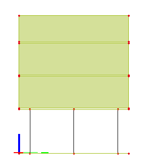
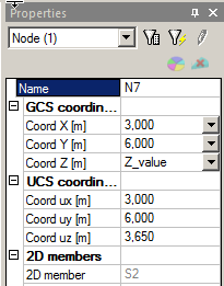
Example 1
- In the following example there is a node (N12) with Z coordinate defined by a parameter.
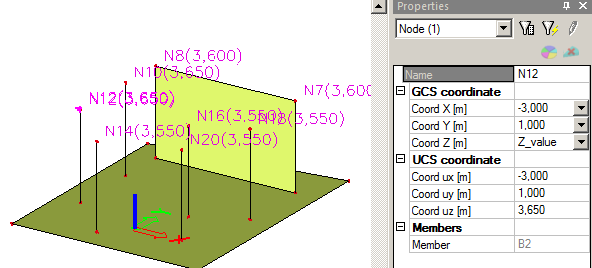
- Select Planes of parametrical input as a master plane.
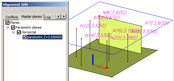
- All nodes are aligned into the plane with the Z coordinate 3.6m.
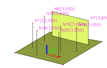
- If the option Parameterize the structure by master planes is selected, the Z – coordinate of all nodes in the plane has defined the proper parameter.
Example 2
- For a project where a line grid is inputted select option Line grid planes.
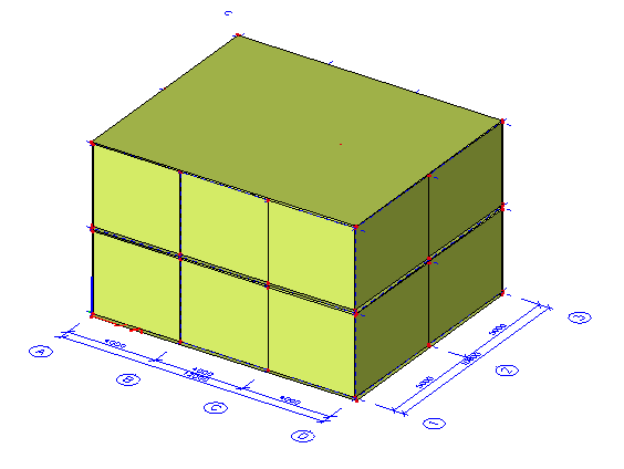
- All planes are displayed.
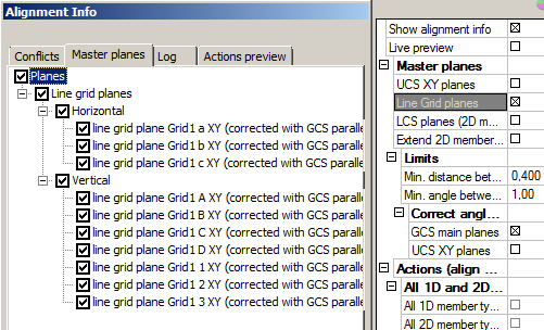
- The structure is aligned.
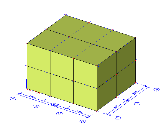
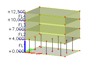
Example 3
- Storeys are defined in an imported project.
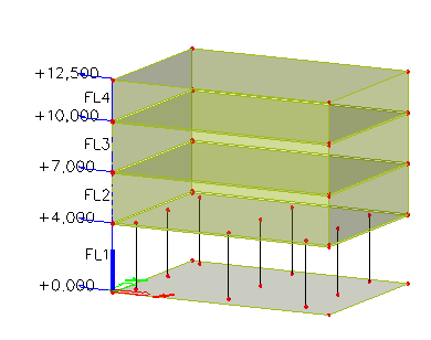
- Select the option Storey planes.
- The structure is aligned horizontally according to the defined storeys.
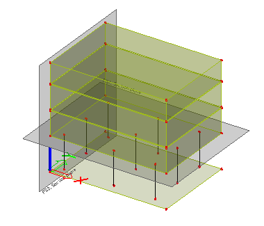
Example 4
- Section planes are defined in the project.
- Select Section planes as master planes.
- Run Align function. Elements fitting into one of the planes are aligned and connected.
Example 5
- Select LCS planes for both, 1D and 2D members.
- Select some actions, e.g. Columns to plates and Walls to walls.
- Select Live preview.
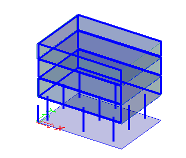
- Confirm the action with [Run Align] action button.
- All walls are connected together and columns extended to plates. The rest of structure is not aligned.