FEM - expected differences - New 2D element formulation since 21.1. patch 2
Introduction
This chapter is to inform about possible expected differences of the results between SCIA Engineer versions.
New 2D element formulation in 21.1. patch 2
A new 2D element formulation has been introduced since 21.1. patch 2. This might cause differences between results of models calculated in previous versions and the newer versions of SCIA Engineer.
Older element (before 21.1. patch 2) had internally 5 nodes (rectangle with 4 edge nodes + 1 additional in the middle). Hence internally (by FEM solver) it was in topology way more closer to 4 triangles. In SCIA Engineer, the internal node was not plotted to avoid confusion.
New finite element is 4 nodal. Finer mesh is required in order to obtain satisfactory results. For new projects, the default mesh size is altered. For older projects created in previous versions, this needs to be handled by the user.
Example of old vs. new 2D finite element performance
A concrete slab with a rib has been modelled - geometry see figure below. Self weight load case is analysed.

Old finite element, edge size 1 m:
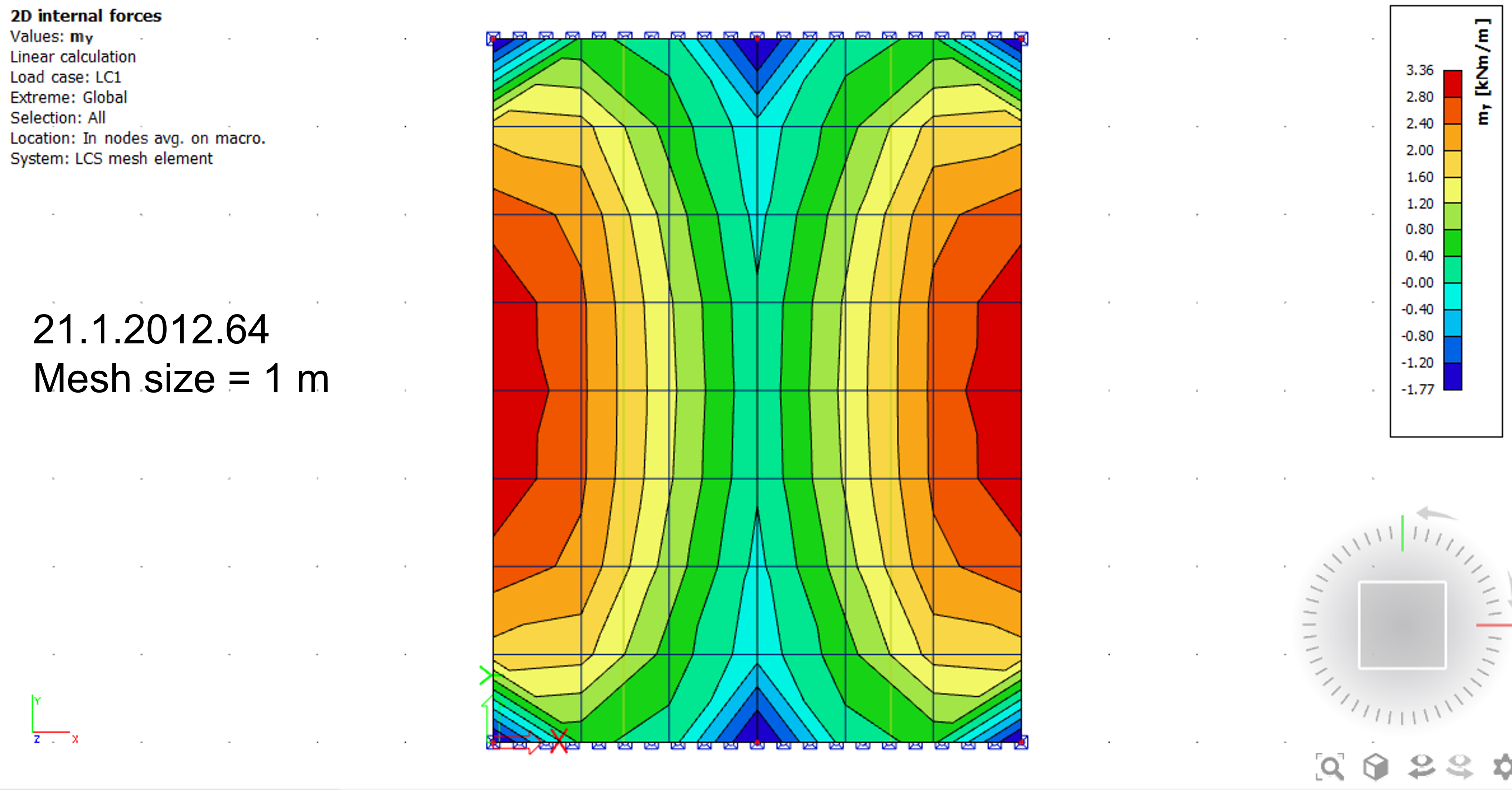
New element, edge size 1 m (the difference is in singularity):
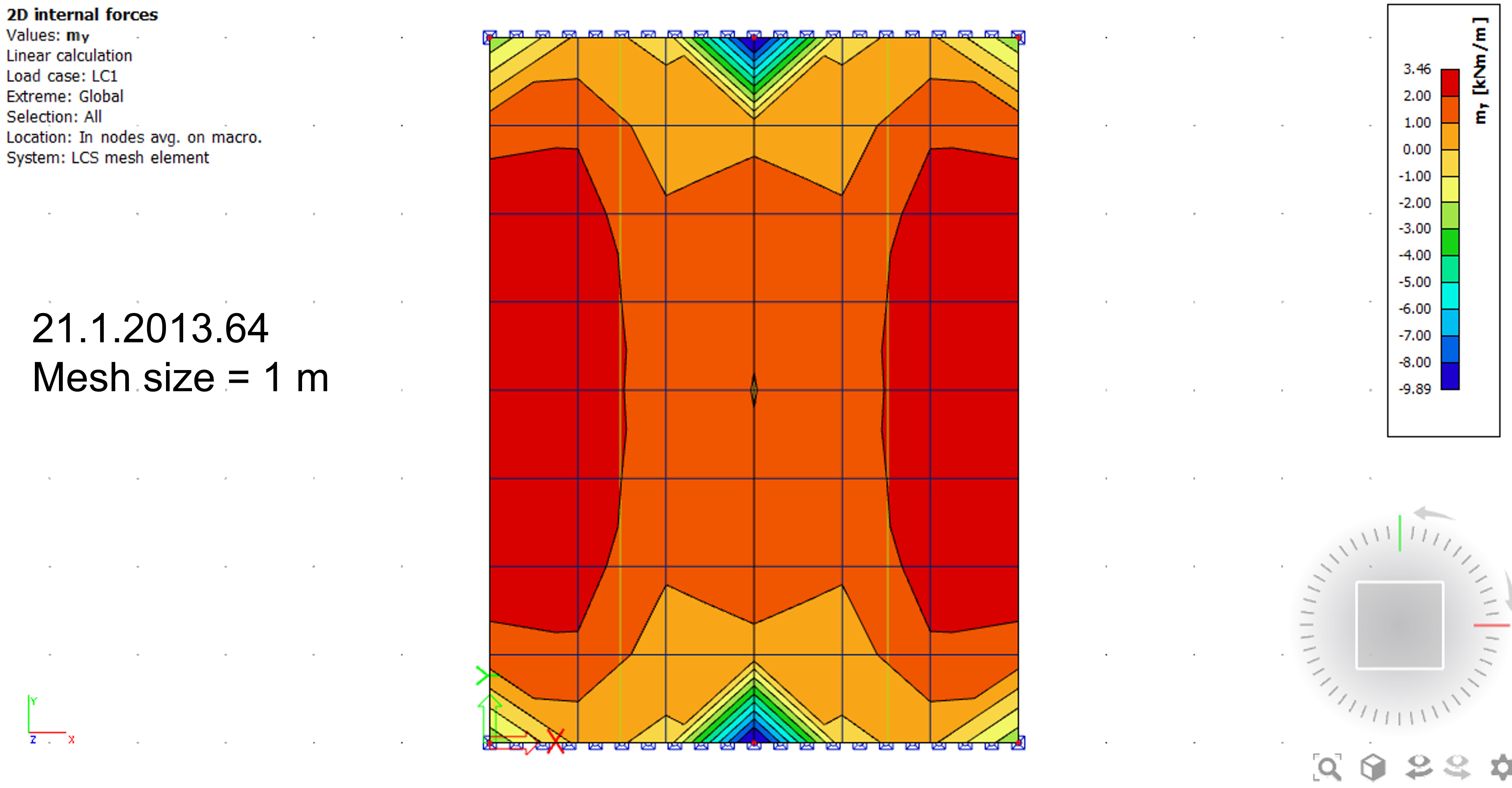
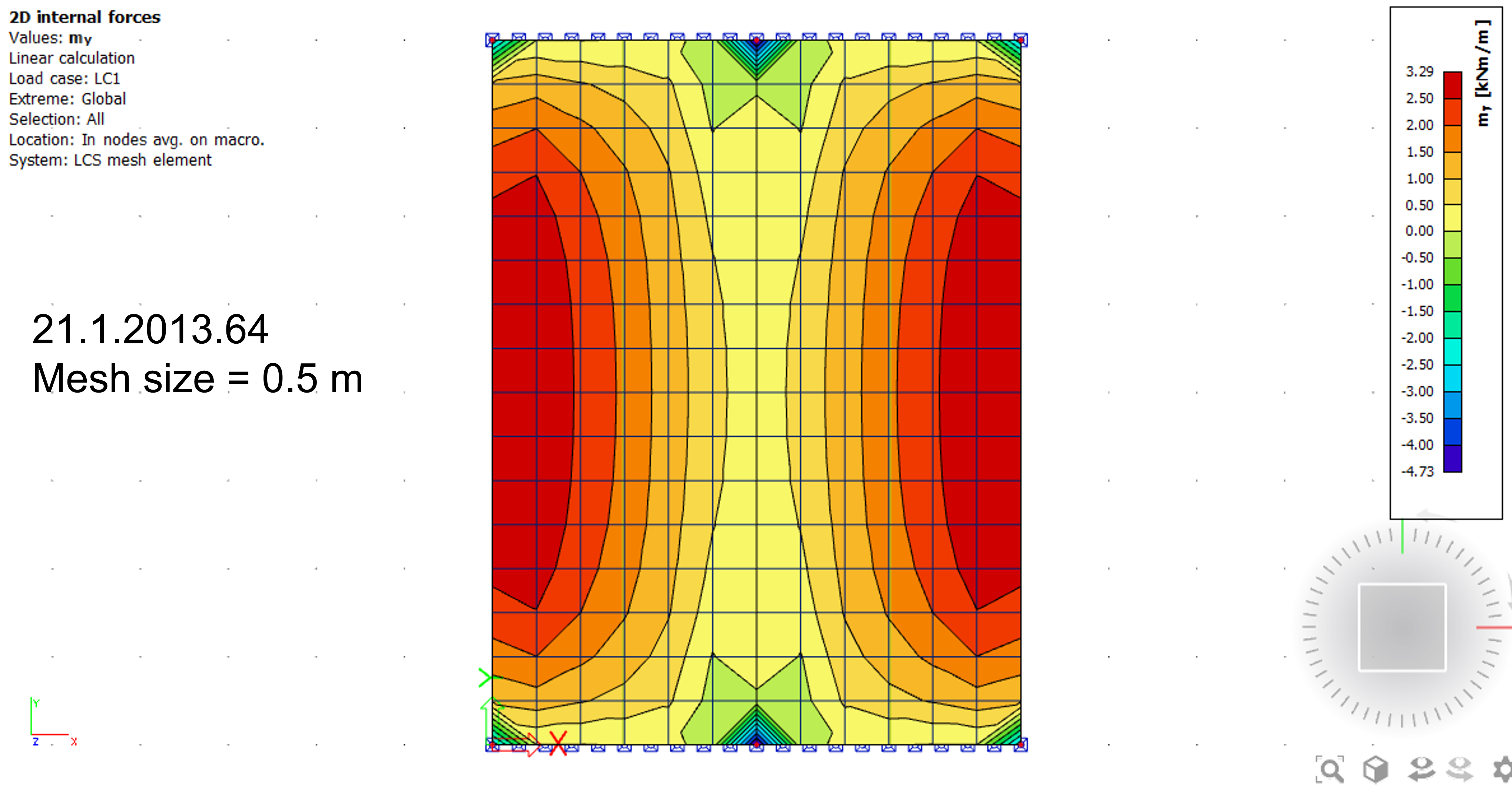
New element, edge size 0,5 m (still the difference in singularity, but smaller):
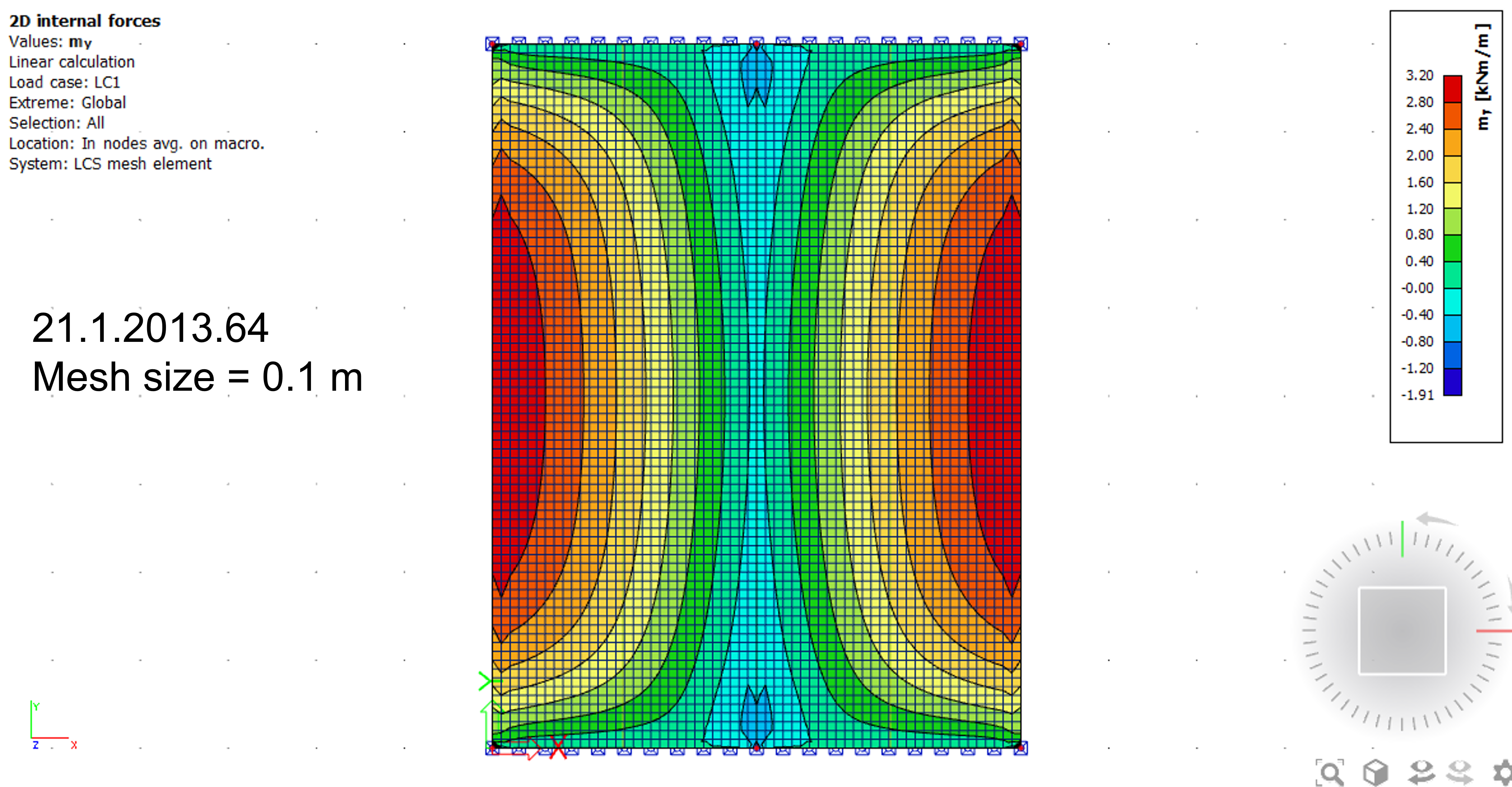
Old element, edge size 0.1 m
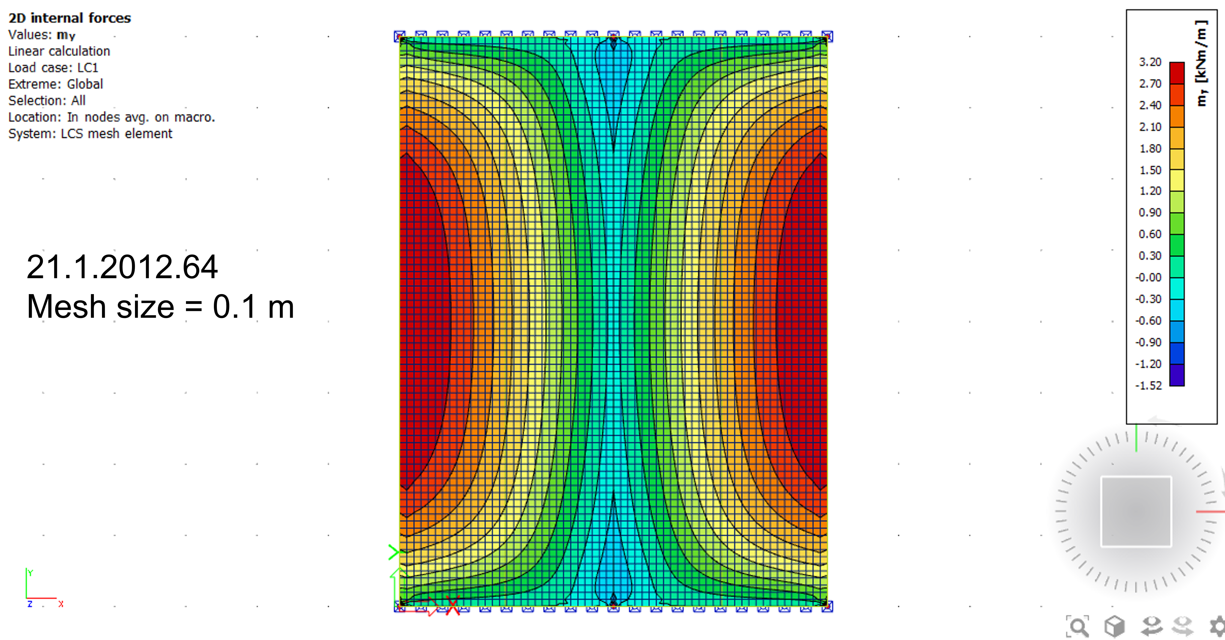
New element, edge size 0.1 m (results are very similar, still little difference in singularity):
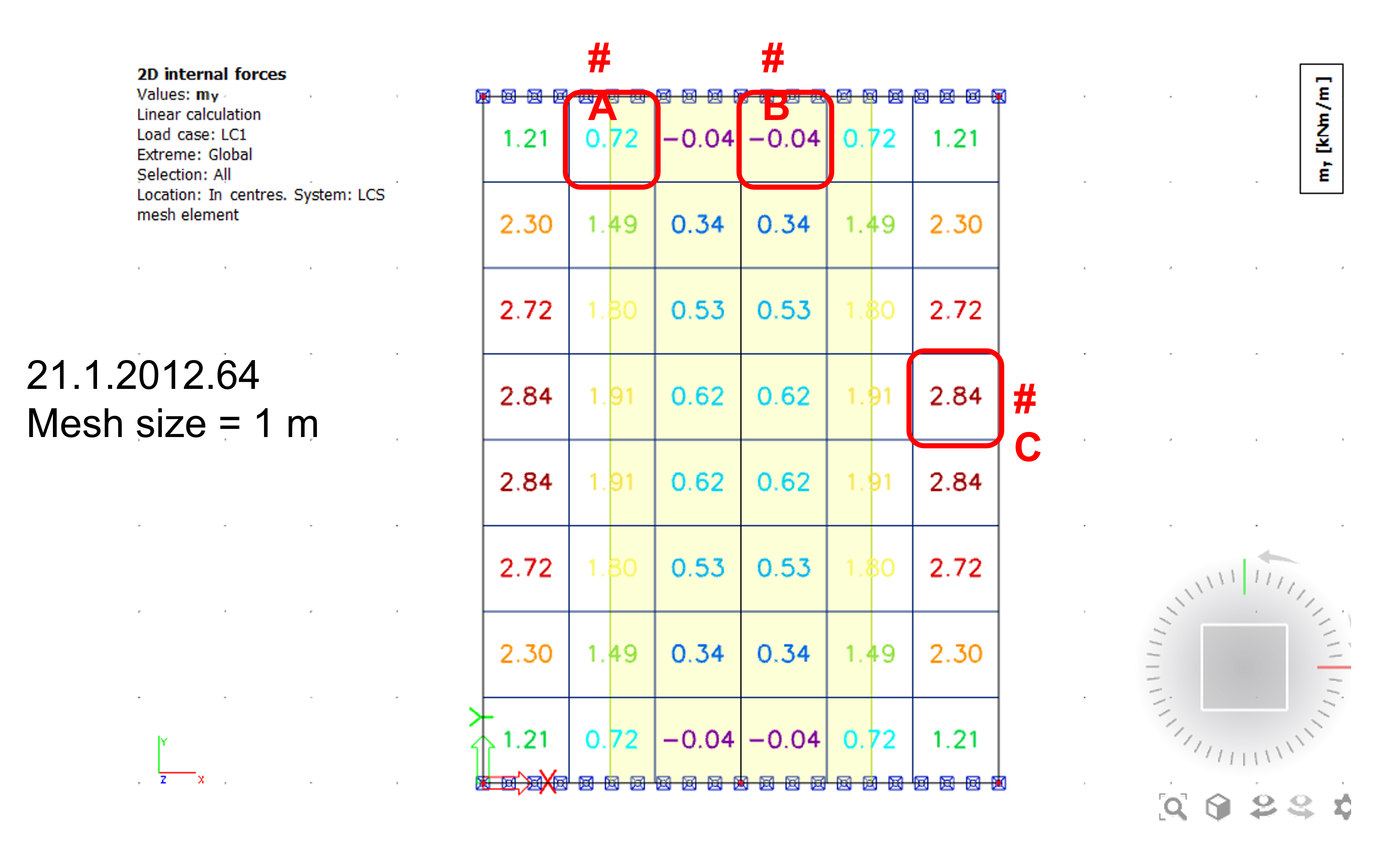
Old element, edge size 1 m, averaged results in centres of the elements:
New element, where the mesh shape was altered in order to look similar to what is considered by solver internally. Internal edges have been utilized in order to force the mesh into triangle shape. This comparison is not exact, only approximate - if the values (from centres of the elements) are averaged, similar value to the value obtained while utilizing the old element is achieved. Some difference near the singularity point still remains (the point where end of rib is supported).
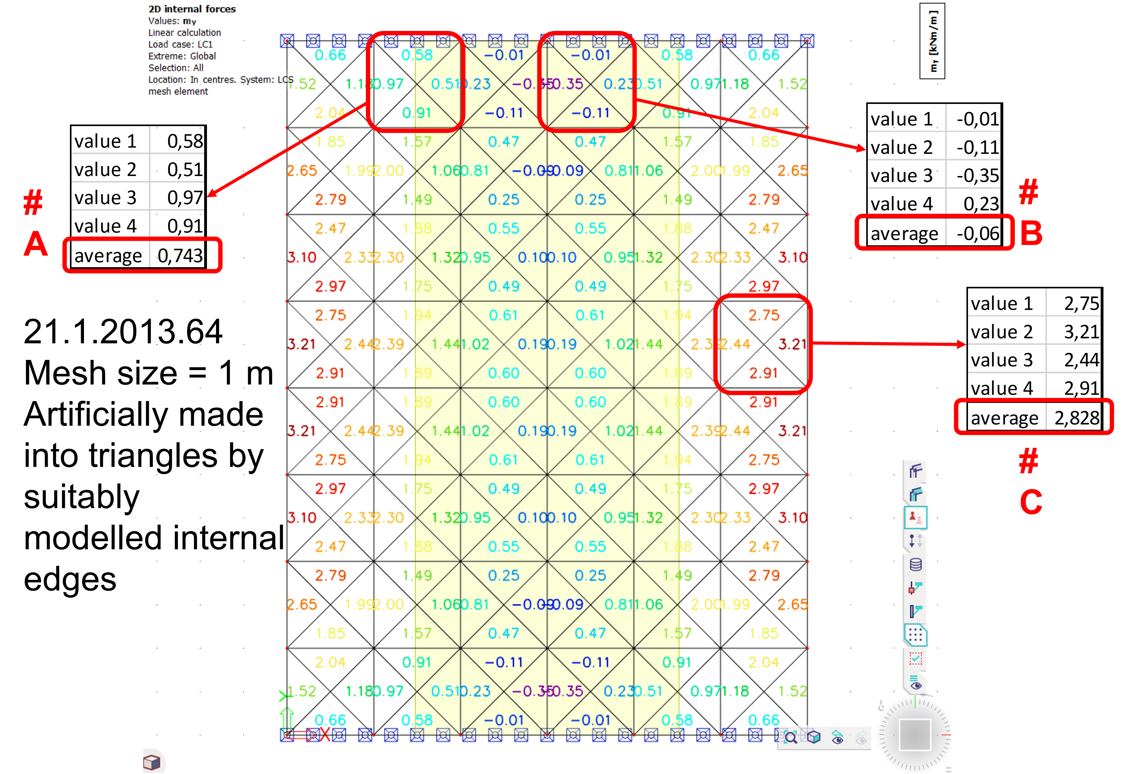
Note: This behaviour is correct according to the logic of finite elements.
Example: new 2D finite element performance on slab with orthotropy - slab acting in one direction
In this example, performance of this new 2D element on slab with orthotropy is shown. If the slab is acting practically on one direction only - e.g. one of the bending stiffness D11, D22 is significantly larger than the other (in example below D11 >> D22, hence the slab acts dominantly in the local x direction), the mesh need s to be finer in order to achieve satisfying results.

In case the 2D mesh element size is 0.5 m, the results (displacements in z direction) might be zig-zagged:

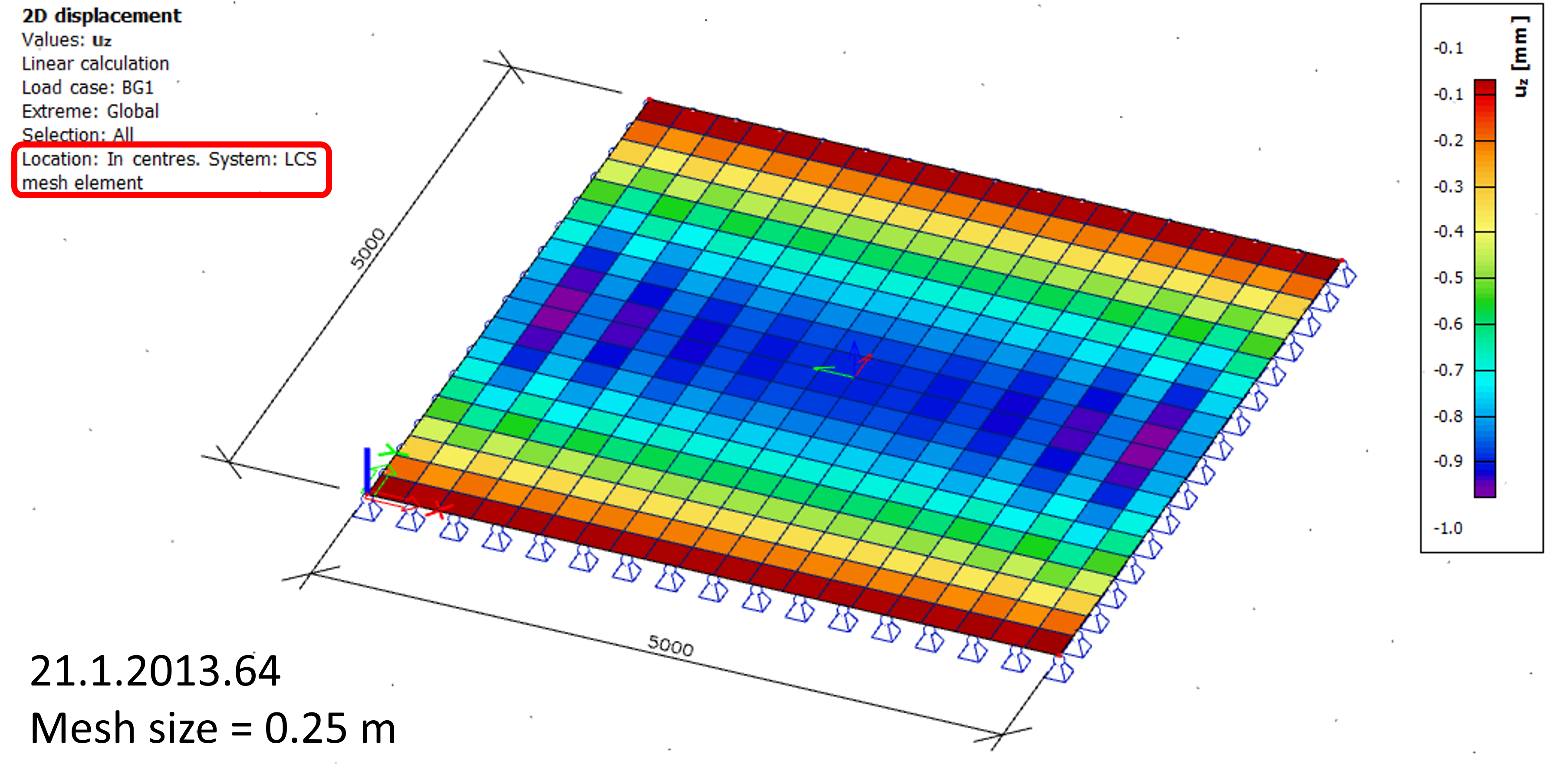
In case finer mesh is used, in this case 0.25 m, the results are smoother, but not yet fully as expected:
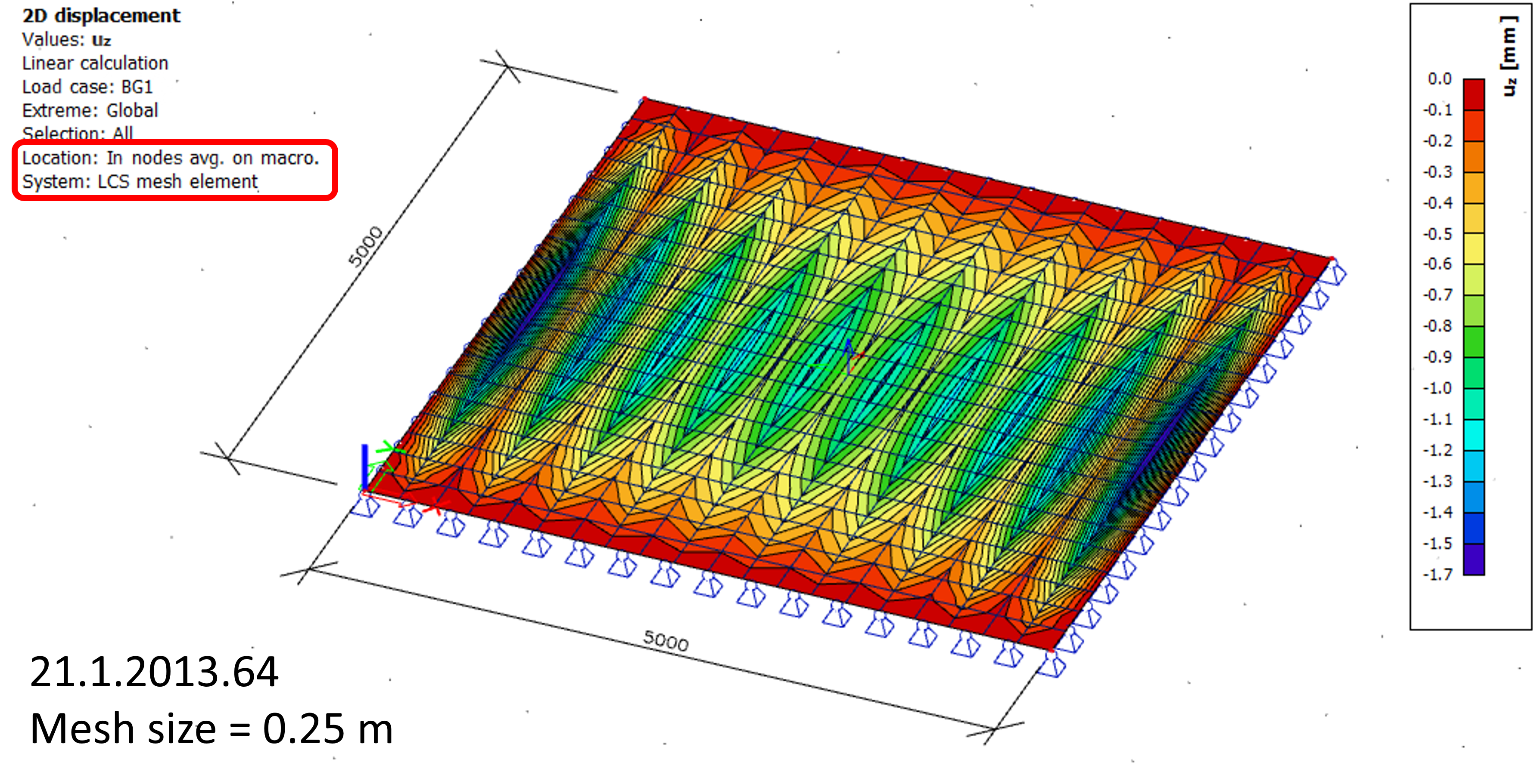
Instead of the averaged results in nodes, averages per mesh element (in centres) might be considered, where the results are smoother:
Or, if even finer mesh is used, as 0.1 m, the results are not zig-zagged any more, and are pretty smooth:
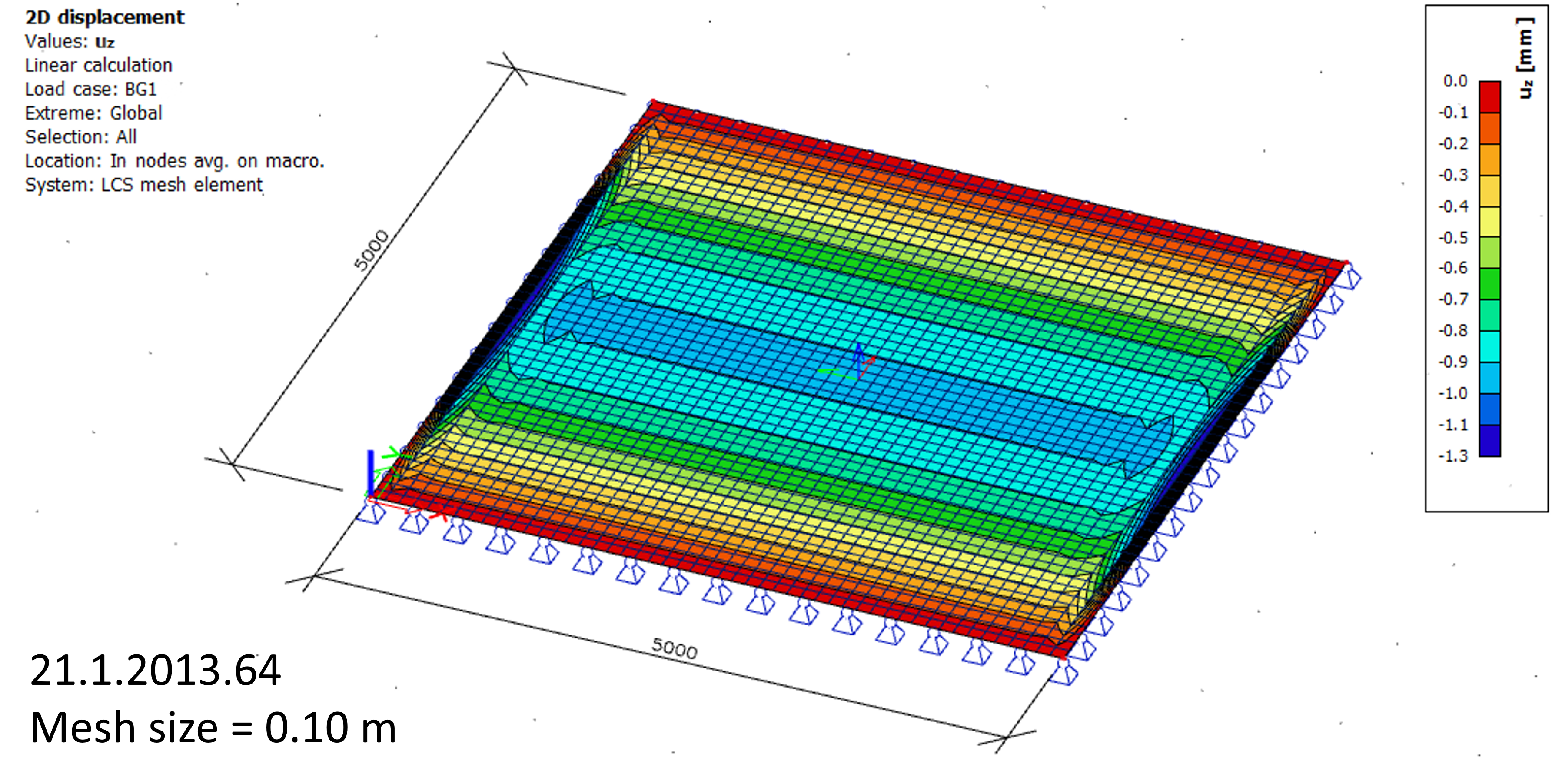
Even finer mesh would lead to more smoother results, but might be less effective while analysing larger structures.