3 Type “Two heights”
This is a special orthotropic continuum for 2D structures of Mindlin type (thick plates). The basic idea follows from the engineering idea of a 2D reinforced concrete member, the stiffness of which can be principally derived from two (generally different) member heights h1, h2 in two characteristic / principal orthotropic directions (x, y)p. The values of h1 and h2 can be derived from a more or less sophisticated numerical reformulation of a geometric orthotropy which appears, for example, in plates stiffened by ribs, or they can represent an approximation of the behaviour of a 2D member in cracked state near its bearing limit (in German literature is it is called State II of a reinforced continuum) which makes the different reinforcement percentages in both directions the main stiffness characteristics (instead of the gross concrete section in the linear State I).
Mathematical description of orthotropy model
Flexural orthotropy
The formulation of a flexural orthotropic continuum is based on flexural stiffnesses of the Kirchhoff type in the principal orthotropy directions:
Flexural stiffness in direction xp [MNm/m] (1)

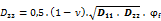
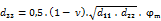
Flexural stiffness in direction yp [MNm/m] (2)

Transverse contraction xp — yp [MNm/m] (3)

Torsion stiffness related to (x,y)p [MNm/m] (4)
Shear flexural stiffness in direction xp [MN/m] (5)

Shear flexural stiffness in direction yp [MN/m] (6)

Membrane orthotropy
In the Wall model the membrane stiffnesses (4 parameters) play the role of the flexural ones in the Plate model. The most general Shell model defines both parameter sets simultaneously (in total 10 orthotropy parameters):
Normal membrane stiffness in direction xp [MN/m] (7)

Normal membrane stiffness in direction yp [MN/m] (8)

Transversal contraction xp—yp [MN/m] (9)

Shear membrane stiffness related to (x,y)p [MN/m] (10)
Symbols in flexural formulae (1) – (6):
Alternatively applied symbols in the membrane stiffness formulae (7) – (10):
| h1, h2 | Statically effective cross-section heights in orthotropy principal directions (x,y)p for membrane resistance. For example, the gross cross-section height in one orthotropy direction, modified in the other direction etc. |
| ϕm | Membrane shear reduction coefficient; using ϕm — 0, the so called “shear-week” wall models can be simulated, e. g. aimed at excluding such members (maybe masonry walls!) from the horizontal stiffening system of the construction |
Discussion of the formulae (1) – (6):
(1) Parameters D11 (1) and D22 (2) are what is known as Kirchoff flexural stiffnesses and are thus self explanatory. Symbols d1 and d2 represent some characteristic heights associated with the principal orthotropy directions, e.g. the cross-section height(s) (both or one of them modified) or the statically effective heights of the two conjugated slab directions or other values;
(2) Shear stiffnesses D44 (5) and D55 (6) are related, in the sense of the Mindlin model, merely to the cross-section area and not to the effective shear height, which is usual in most shear proof procedures. In the present orthotropy model it is assumed that formulae (4), (5) use the same reference heights d1 and d2 as the flexural stiffness formulae (1) and (2);
(3) D33: this is the most discussed stiffness parameter. If D33 is reduced by means of ϕf, the torsion stiffness of the slab diminishes relatively to the coordinate axes, which are also the principal orthotropy axes. D33 = 0 signifies a complete lack of torsional stiffness; such a slab can resist any torsion moments mxy. Thus, no Kirchhoff’s lifting corner forces can develop; this phenomenon may be the primary reason for use of such class of models. As a fact, SCIA Engineer does not allow the user to set any exact zero value. However, values till 5 % (ϕf = 0.05) have proven to yield numerically stable results. It means that there ought to be set a lower input limit for ϕf in the SCIA Engineer input control procedure.