Factors C1, C2 and C3
The coefficients C1, C2 and C3 can be calculated according to three different methods:
ECCS 119/Galea
Lopez, Yong, Serna
ENV 1993-1-1 Annex F
By default the method according to ECCS 119/Galea is applied.
The following paragraphs give information on these methods.
ECCS 119/Galea
When this setting is chosen, the moment factors are determined according to ECCS 119 Annex B Ref.[9].
The figures given in this reference for C1 and C2 in case of combined loading originate from Ref.[28] which in fact also gives the tabulated values of those figures as well as an extended range.
The actual moment distribution is compared with several standard moment distributions. These standard moment distributions are moment lines generated by a distributed q load, a nodal F load, or where the moment line is maximum at the start or at the end of the beam.
The standard moment distribution which is closest to the actual moment distribution, is taken for the calculation of the factors C1 and C2.
Linear Moment
In case of a linear moment diagram the C1 coefficient is determined using formula (301) of ECCS 119 Annex B Ref.[9].
The coefficient C2 is taken as zero in this case.
Point Loading
In case of Point loading the coefficients C1 and C2 are calculated using tables 5-8 of Galea Ref.[28].
A double interpolation is used for intermediate values.
Line Loading
In case of Line loading the coefficients C1 and C2 are calculated using tables 1-4 of Galea Ref.[28].
A double interpolation is used for intermediate values.
In case k differs from 1.00 the C1 and C2 values determined from Galea Ref.[28] are overruled by the values from ECCS 119 Annex B Ref.[9] tables 63 and 64
For all cases the factor C3 is taken from ECCS 119 Annex B Ref.[9] tables 63 and 64. The C3 value is determined based on the case of which the C1 value most closely matches the table value. In case of a moment diagram for end moment loading: table 63 is used. In case of a moment diagram for line loading or point loading: table 64 is used.
The table for C3 uses the value ψf which is taken as 0 by default.
For asymmetrical I-sections (Form code 101) ψf is calculated as follows:

Ifc and Ift concern the moments of inertia of the compression ( c ) and tension ( t ) flange about the minor axis.
For this method ψf should be within the following range:

When this is not the case ψf is set to the respective limit and a warning is given.
I-section Cantilevers
ECCS 119 Annex B Ref.[9] tables 65 to 68 give values for C1, C2 and C3 for I-section cantilevers.
These coefficients are used only in case the following conditions are met:
- The member concerns a cantilever.
A cantilever is defined as a member at the end of a buckling system which has free ends for both buckling about the y-y and z-z axis. In addition, the LTB length should correspond to the full system length of the buckling system.
This method differentiates between ‘warping prevented’ and ‘warping free’ at the fixed end. This setting is taken from the buckling system.
This method uses the value ψf which is calculated as specified above.
For this method ψf should be within the following range:

When this is not the case ψf is set to the respective limit and a warning is given.
This method uses the coefficient  which is defined as follows:
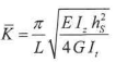
with:
| L |
System length for LTB |
|
E |
Modulus of Young |
|
G |
Shear modulus |
|
Iz |
Inertia about the weak axis |
|
It |
Torsion constant |
|
hs |
Distance defined as follows: Form Code 1: H - t Form Code 101: H – 0,5 * tt – 0,5 * tb |
should be within the following range:

When this is not the case is set to the respective limit and a warning is given.
In addition this method should be used in combination with k equal to 2,00 and kw equal to 1,00
When this is not the case an additional warning is given.
Lopez, Yong, Serna
When this setting is chosen, the moment factors are determined according to Lopez, Yong, Serna Ref.[29].
When using this method the coefficients C2 and C3 are set to zero.
The coefficient C1 is calculated as follows:
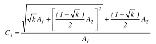

With:
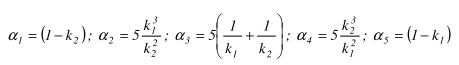
| k1 |
Taken equal to kw |
|
k2 |
Taken equal to kw |
|
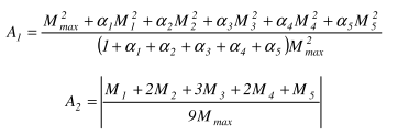
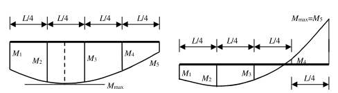
M1, M2, M3, M4, M5 |
The moments My determined on the buckling system in the given sections as shown on the above figure. These moments are determined by dividing the beam into 10 parts (11 sections) and interpolating between these sections. |
|
Mmax |
The maximal moment My along the LTB system. |
This method is only supported in case both k and kw equal 0.50 or 1.00
ENV 1993-1-1 Annex F
When this setting is chosen, the moment factors are determined according to ENV 1993-1-1 Annex F Ref.[10].
Detailed information can be found in chapter "Annex C: Calculation of moment factors for LTB".