Initial stress - options
The analysed structure may be subject to an initial stress. This may be defined in several ways. The approach can be adjusted in the Solver options setup dialogue: Advanced solver settings - initial stress. By default, the initial stress is deactivated (Figure below, #A).
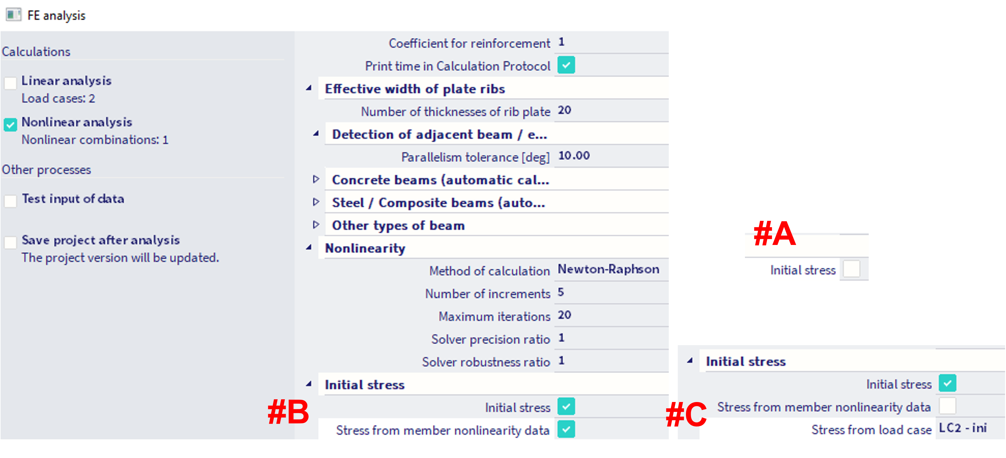
There are two options how to consider the initial stress:
Initial stress from member nonlinearity data (Figure above, #B)
More detailed information is found in this chapter.
Initial stress based on load case (Figure above, #C)
The initial stress may be calculated from the results of selected load case. The results of linear static calculation for the specified load case are used to determine the initial stress in the beam.
Initial stress based on load case - example
The initial stress based on certain LC is internally considered as additional load case (with multiplier of 1.0) within the content of each user defined nonlinear combination in the project. Moreover, an initial state analysis is being internally calculated and used as the initial state for the subsequent nonlinear combinations. Example of this behaviour along with results is provided below on a simple model.
Example
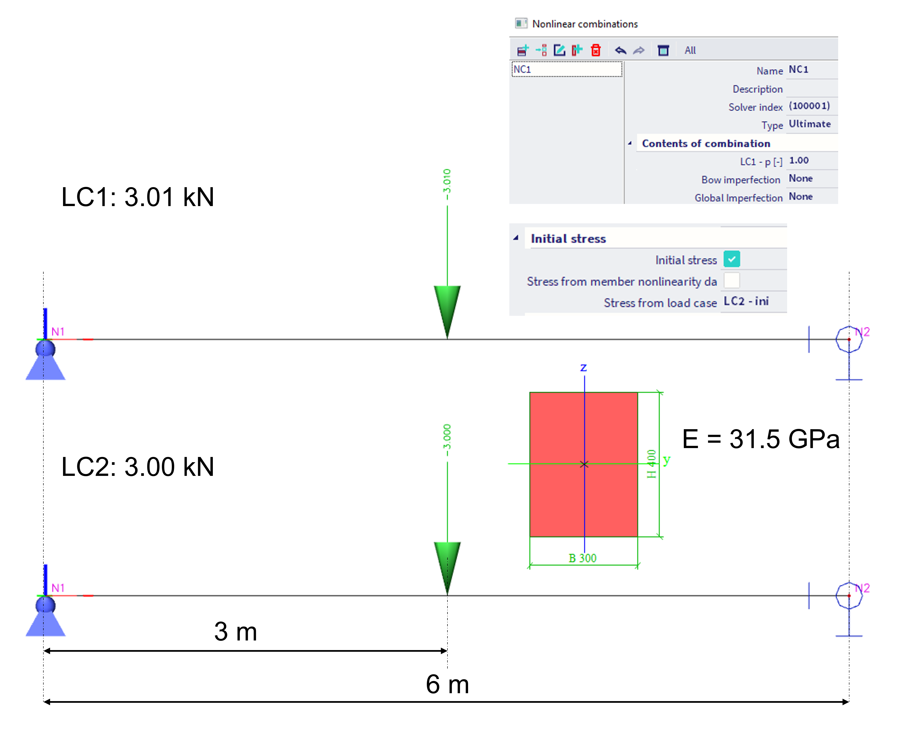
Example of the internal behaviour of this feature is shown on a model of a simply supported beam, which geometry is depicted in the figure below. There are two load cases defined, LC1 with the point force of 3.01 kN in the mid-span, and LC2 with 3.00 kN in the mid-span of the beam. The load case LC2 is used as load case to determine the initial stress. There is one nonlinear combination NC1, which contains only LC1 (with multiplier of 1.0).
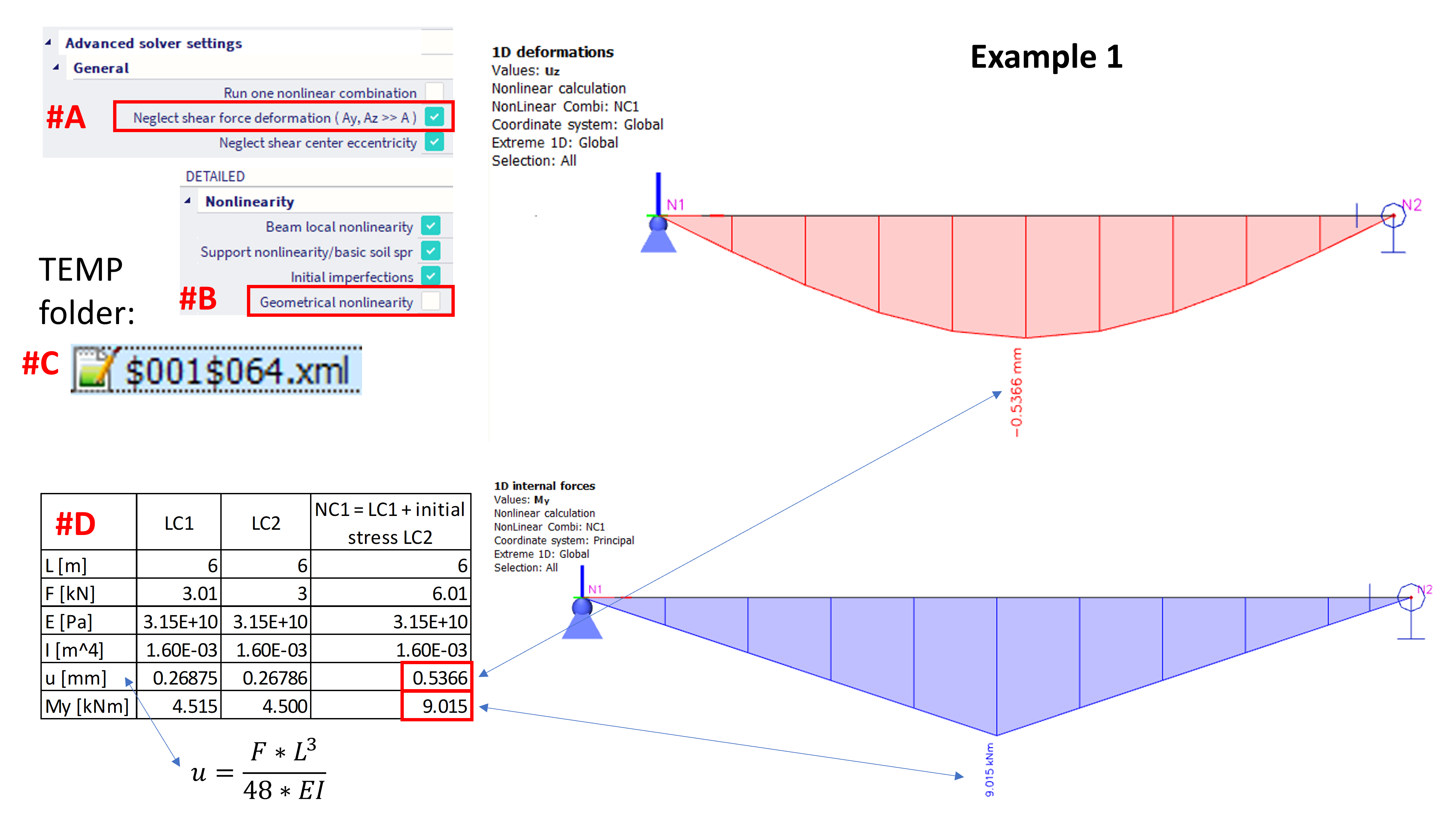
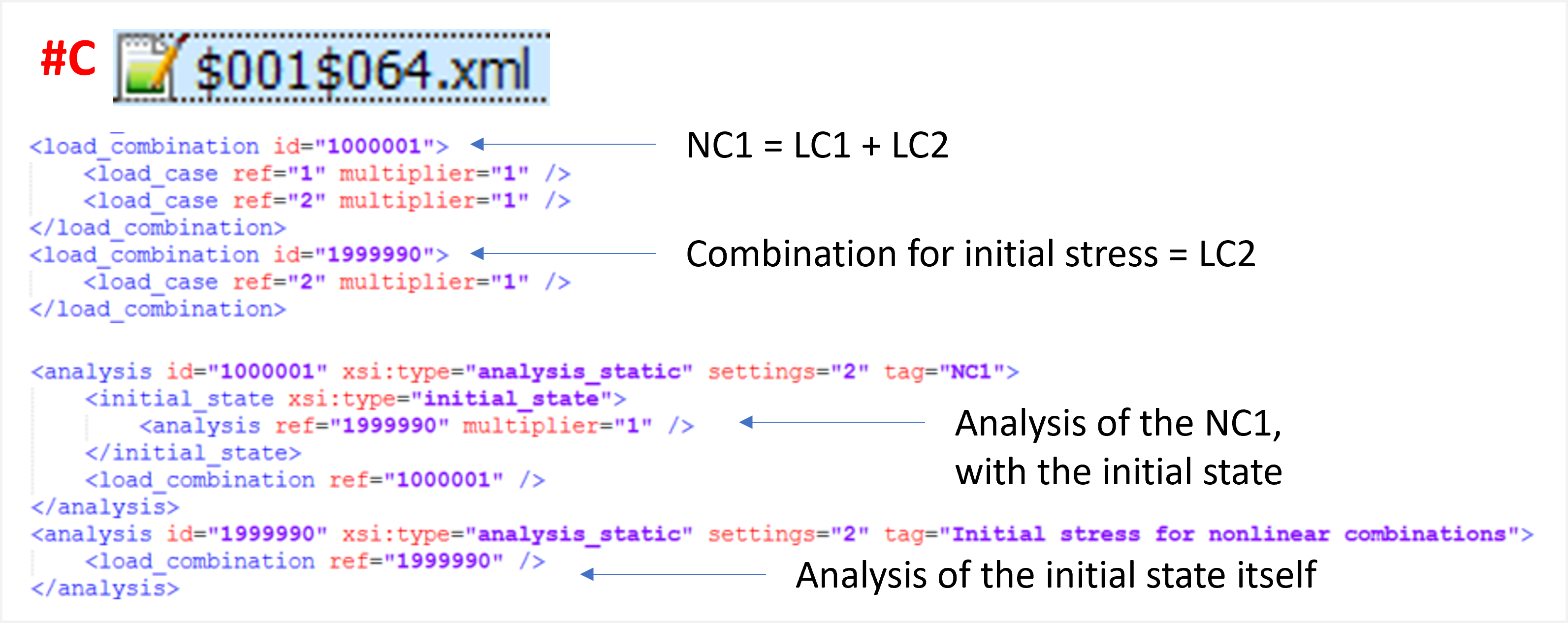
In order to get the match between hand calculation and results in SCIA, the shear force deformation is neglected in this example (#A). Furthermore, in order to compare the results of linear load case and the nonlinear combination, the geometrical nonlinearity is turned off (#B), so the superposition of the results might be considered (the deformations in this example are rather small). It is shown, how was this considered internally in the software (#C) - in the SCIA TEMP folder, in the corresponding *.XML* file, the nonlinear combination contained two load cases - LC1 which is explicitly defined by the user, and LC2 which is set by the user as initial stress. This is comparable to case, as if there was no initial stress defined by the user at all, and the content of the nonlinear combination NC1 was set as 1*LC1 + 1*LC2. Such results corresponds with the hand calculation (#D).
How the combination is considered internally might be checked in the corresponding *.XML file from TEMP folder:
The results are summarized in the figure below.
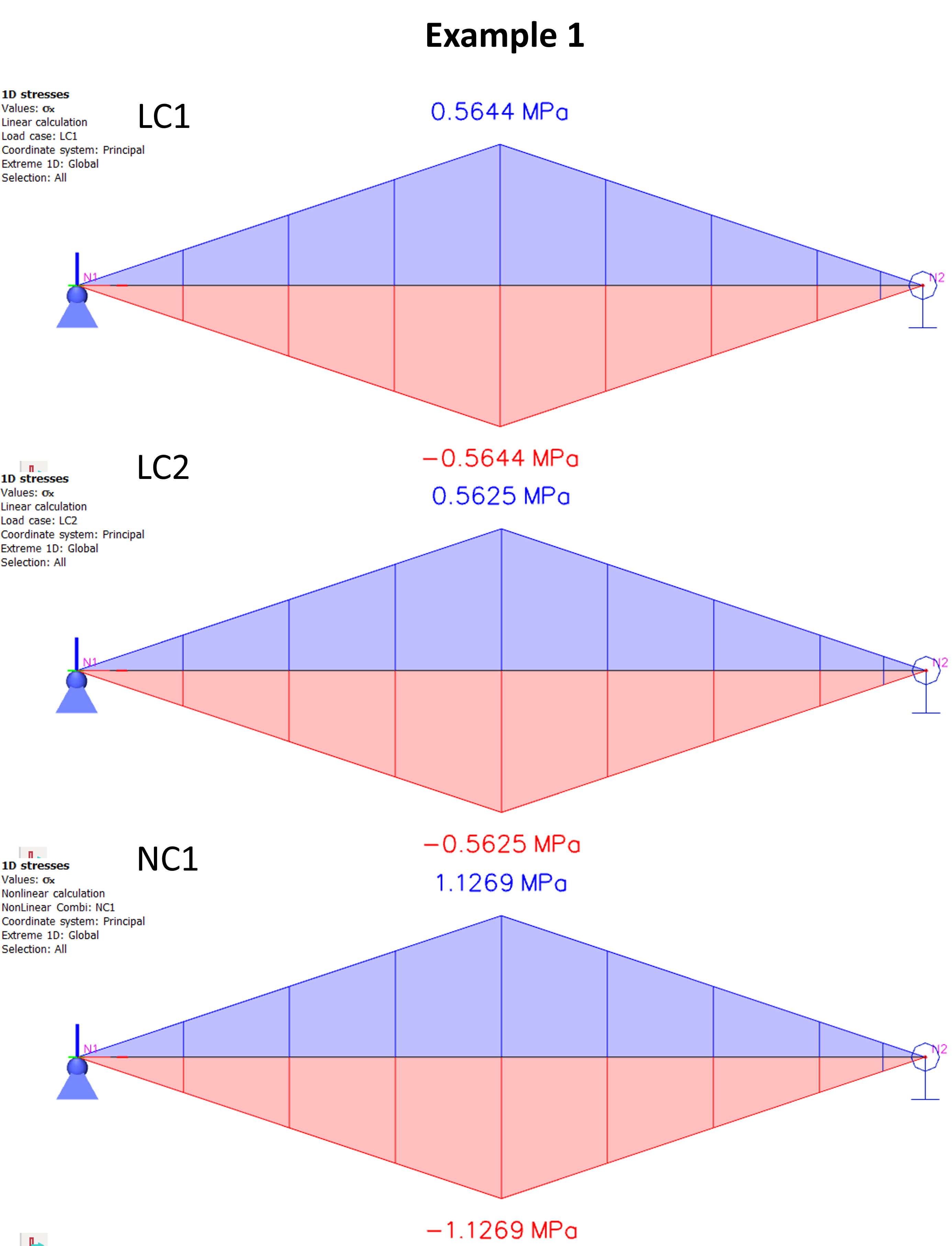
Note: In short period since version 24.0, the results were slightly different, as there was a different behaviour of the FEM solver (the deflection of the above mentioned case of the NL combination was 0.26875 mm, so the same value as for the LC1. The My and stress results were the same as now).