Footfall loads – defining location exposed to footfall
The load defined in the Footfall load case is not a standard static load, as it does not directly represent forces or moments used in static analysis.
Instead, it serves to define the area of the structure exposed to pedestrian movement.
This load indicates where pedestrians walk, allowing SCIA Engineer to subsequently calculate the structural response caused by pedestrian movement in that area.
Why is this defined as a load case?
Even though this is not a traditional load, it is implemented as a load case because the footfall analysis requires defining specific locations (points, lines, surfaces) on the structure where pedestrians are present.
This way you can use the same tools you already know for assigning loads and apply them to define the area exposed to pedestrians.
Available load types
Only specific load types can be used in the footfall load case, corresponding to the ways pedestrians can distribute their weight on a structure:
-
Point load on 1D
-
Line load on 1D
-
Line load on 2D edge
-
Surface load on 2D
-
Free surface load
These load types correspond to pedestrian distribution at a single point, along a line, or over an area.
Footfall load modelling and key parameters
Applying loads in the Footfall load case is similar to applying loads in a standard static load case.
The only differences are in certain options for defining the load. These differences are described in the following separate subchapters.
Free surface load
Footfall loads are always applied at finite element nodes. When using a Free Surface Load, the surface load is automatically applied to all nodes of any affected element. Even if the load covers only part of an element, all four of its nodes will receive the footfall load.
This effect is most noticeable in Self Excitation mode, where the response appears only at nodes being excited. In the figure below, the generated free load is shown, and the red circles mark all nodes belonging to the elements that are fully or even partially covered by the free surface load.

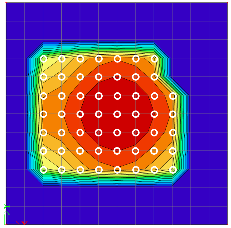
In the results shown in the following figure, it can be clearly seen that responses are calculated for all nodes of the elements on which the free surface load lies at least partially. When results are displayed using isobands, gradual transitions appear between nodes, which is most visible at the boundary nodes. In the results figure, the excited nodes are highlighted in white for better colour distinction (they correspond to the red nodes shown in the previous figure).

Load value settings
As mentioned in previous chapters, the Footfall load case is not a typical load case. Its purpose is solely to define the area where pedestrian loads will be applied.
Therefore, it is not necessary to define any load value in the Footfall load case. For response calculations, pedestrians are represented by mass or weight settings within the load case.
Consequently, no load value will be displayed in the 3D scene.
Load direction limitation
For loads defined in the Footfall load case, only the global Z direction is available.
The X and Y directions cannot be selected.
This limitation exists because the Footfall load case is intended for slabs, where pedestrian-induced loads are assumed to act only in the vertical (Z) direction.
Restricting the direction to global Z ensures a clear and consistent application of weighting factors when the Design Method SCI P354 is used.
It also provides users with full clarity about which weighting curve will be applied, since the selected direction will correspond directly to the results displayed in the analysis.
Eccentricity Settings
It is not possible to assign eccentricity to a load in the Footfall load case.
This option is fixed at 0 and cannot be changed.