7th DoF (warping) - hinges
Introduction
This chapter is to provide a closer information about the behaviour of hinges, if the functionality of the 7th degree of freedom (warping) is considered in the project.
Hinge on 1D member - 7th degree of freedom (warping)
Additional property of the warping is available for hinges on 1D members, and only for these (e.g. nothing extra for line hinges between two edges on surface members - slabs, shells).
Theory
If a hinge is defined at the begin or the end of a beam, the node at this position is being duplicated, and degrees of freedom are transferred between these two nodes respecting the defined constrain conditions of the hinge. This duplication is done for all kind of hinges (not only warping).
Hence, in general, if n-beams meet in one joint, it is not recommended to define hinges of the same type for all the n beams. It is recommended to define for n-1 (at least one beam remains without duplicated node). Otherwise, if all n nodes would be duplicated, there would be one "free" node, which might cause troubles in numerical instability. This is also recommended in we define only warping hinges (note: since version 26.0. patch 2, there is an improvement allowing to define warping hinge of special type to be defined on all the n beams, but overall it is still not recommended for hinges in general).
New property within the hinge on 1D
See example in the figure below. Possible states are: Free (default), Rigid and Flexible. It is not possible to use nonlinear function for the hinge for the warping degree of freedom. Available states are described further.
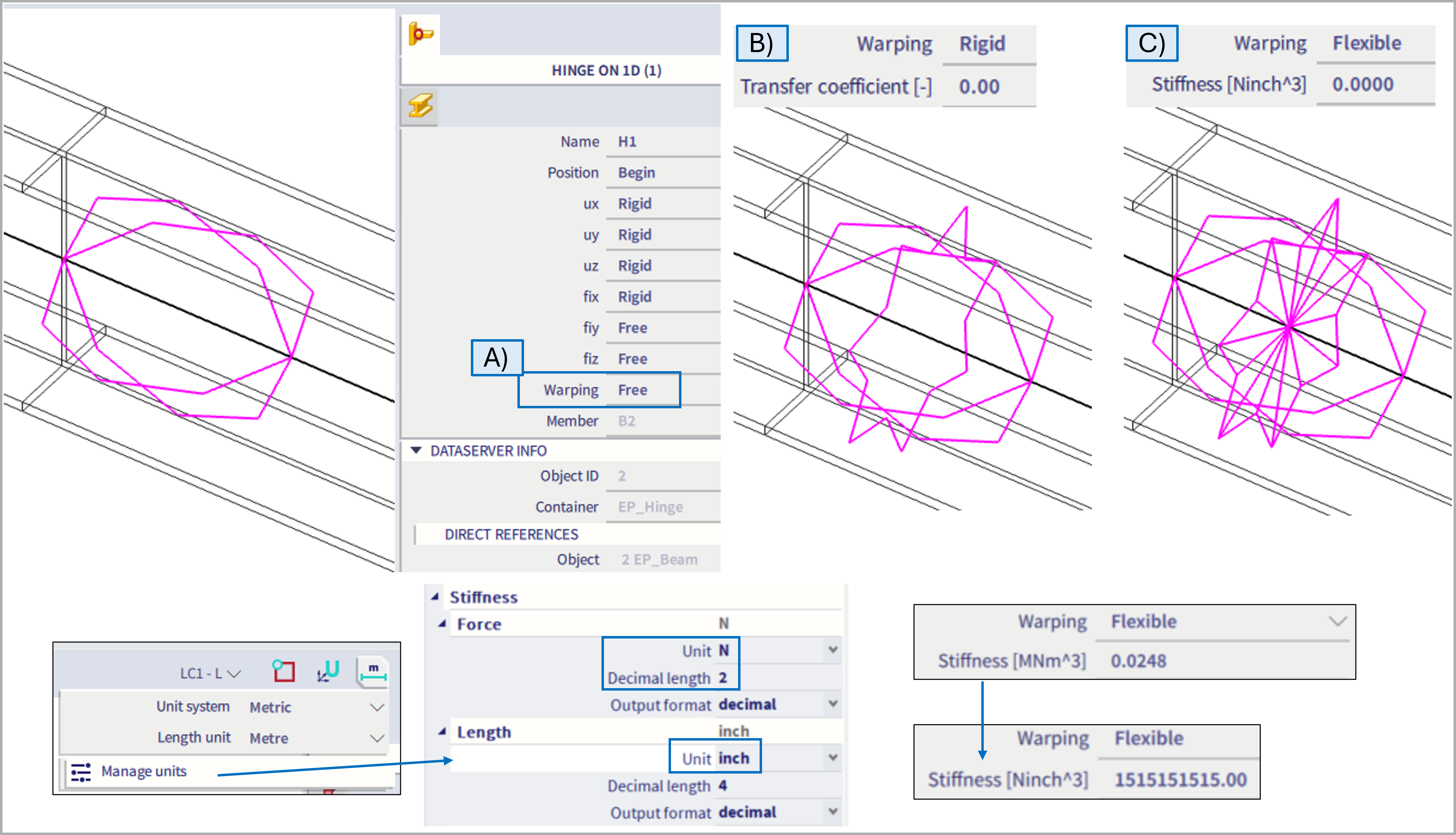
A) Warping = Free
This option is default for any modelled hinge if the 7DoF functionality is activated. Keep in mind, there is no extra graphical symbol depicting this state within the hinge (as the graphical symbols are used for warping ="flexible", and warping="rigid", which is more versatile, and if "rigid" is used within hinge, it makes more sense to graphically distinguish such definition due to its specialities).
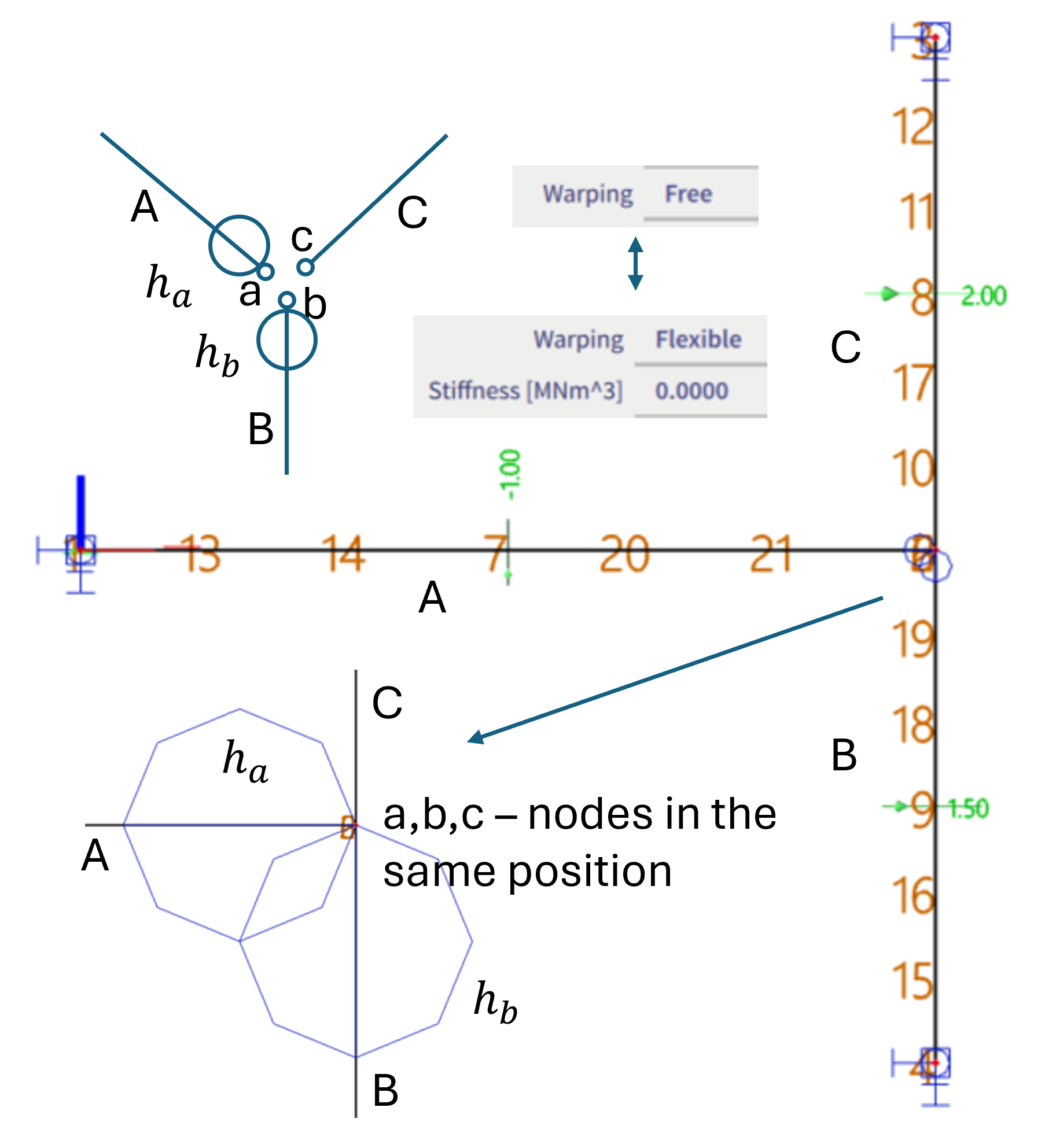
If free hinge is defined, there is no transition of the warping (ω deformation, or also so called deplanation) between the internal nodes of the hinge (the duplicated node and the original as mentioned above in the theory chapter). The hinge with warping = free is analogical to warping = flexible with 0 stiffness.
It is not possible to define 6 DoFs as "rigid" and warping as "free". This is solely due to practical fact, there is no graphical plot for a hinge of such definition, hence such hinge would not be possible to be selected and distinguished in the 3D scene. However, analogical setting of all the 6 DoFs set as "rigid" and warping set as "flexible" with 0 stiffness is possible to be defined, so this state also might be simulated without any problem. Warping might be also set to "free" in case at least one other constrain is set to free (so such hinge is already possible to be selected in the 3D scene).
Note: Above mentioned is not valid for the first iteration of v 26.0 and also 26.0. patch 1 - there was original intention not to export anything into the FEM solver for "warping = free" for the corresponding hinge, but by default, FEM solver considers warping to be fully transferred if not defined otherwise. Hence in these two versions, if the warping parameter for hinge is set to free, it is ignored, and warping is transitioned fully (as if there was warping = rigid with transfer coefficient =1, as explained further below). Workaround in these two versions is to set warping = flexible with 0 stiffness, which is working consistently. This issue was fixed in v 26.0 patch 2. Since this version, warping in hinge set to free does not transfer the ω deformation.
B) Warping = Rigid
If this option is selected, additional parameter of an unit-less "Transfer coefficient" is to be defined (default value = 0.001).
The transfer coefficient, in figure below noted as ka, or kb, is a parameter to define the transition condition between the duplicated nodes of the corresponding hinge. In example below, there are 3 beams intersecting in one joint, A, B and C. If two hinges ha and hbare defined at the end of beam A and B, the nodes a and b are internally duplicated, and as there is no hinge at he beam C, the duplicated nodes from a and b are merged together with node c. Hence, in the end there are three nodes at the same position: a,b and c. In case there would be a hinge at beam C in this joint, node c would be duplicated, and there would be extra "free" node d, which does not belong to any beam (this would be the node which might cause numerical problems in some cases).
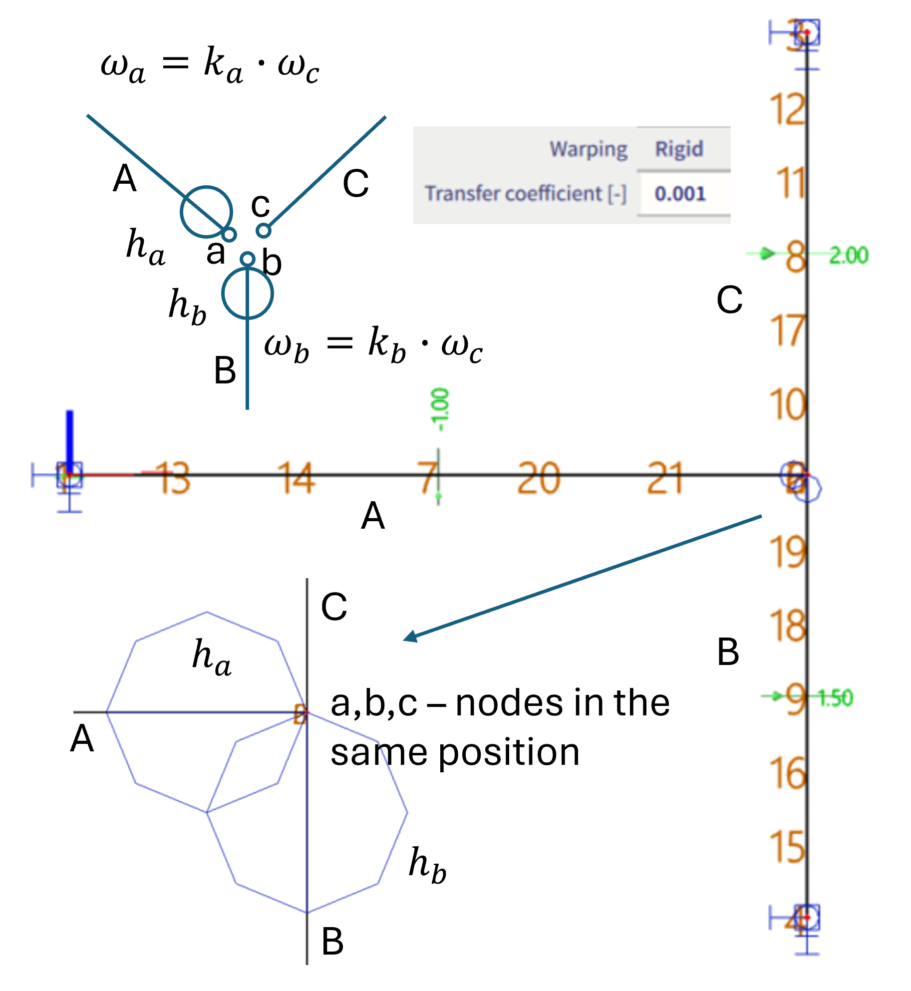
By the transfer coefficient k, the transition condition between the warping deformation ω of two nodes of the corresponding hinge is defined.
If the hinge is assigned at the end of beam A, it is considered by an equation: ωa=ka* ωc, where ka is the transfer coefficient of the hinge ha , and it defines the relation between warping ω of the nodes a and c.
Note: For whole the version v 26.0, it is possible to define exactly 0 (which is also default value) for this transfer coefficient. It is in general working well. However, in some very rare cases it might cause numerical issues, hence since version 27.0, the default value is set to 0.001, and exactly 0 is not possible to be input any more. The major reason of this improvement is in order to be consistent in limit interval of this parameter, as the upper boundary for this coefficient is set to 1000, and the bottom of -1000. However, due to character of this transfer coefficient, it should have also inverse values of these interval boundaries defined to be consistent. Hence the original input interval of version 26.0, which was limited to (-1000 ; +1000) was changed into (-1000 ; -0.001) ∪ (+0.001; +1000) since version 27.0.
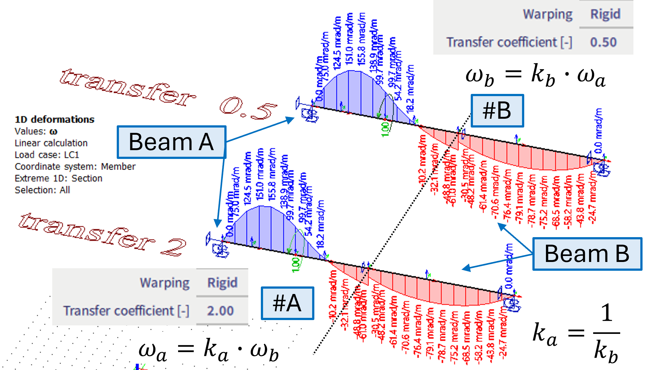
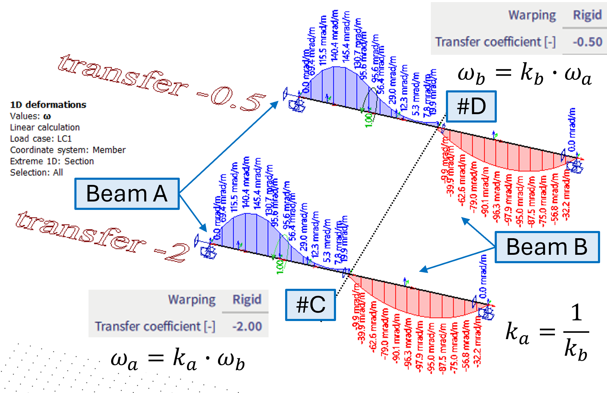
If there are two beams in a joint only, the behaviour is the same whether the hinge is at the end of one beam and transfer coefficient is k, or whether the hinge is defined at the begin of the other beam with transfer coefficient of 1/k. See examples #A #B #C and #D below. The negative value in transfer coefficient determines the opposite signs of the corresponding warping deformations.
#A - the warping hinge is on beam A, with transfer coefficient of 2
#B - the warping hinge is on beam B, with transfer coefficient of 1/2
#A and #B are identical
#C - the warping hinge is on beam A, with transfer coefficient of -2
#D - the warping hinge is on beam B, with transfer coefficient of -1/2
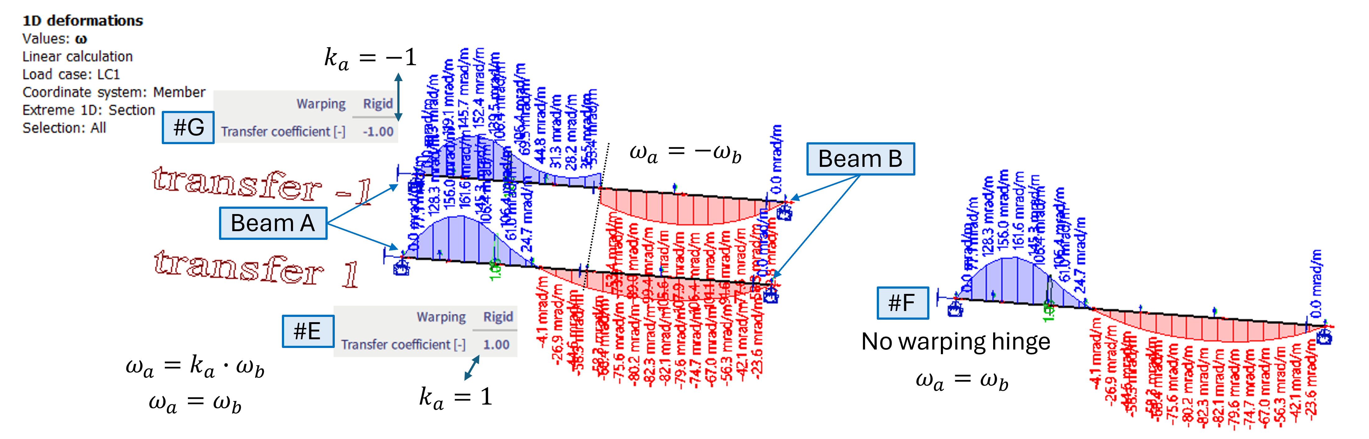
The transfer coefficient of 1 is the same as if there is no hinge at all.
#E - the warping hinge is on beam A, with transfer coefficient of 1
#F - no hinge at all (by default it behaves the same as if there is transfer coefficient 1)
#G - just example of transfer coefficient -1
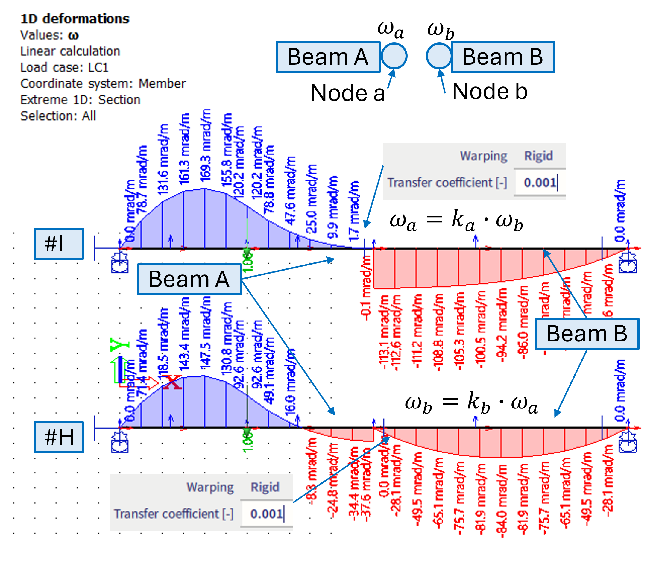
If the warping ω is not to be transferred, practically it might be achieved also by the small value of the transfer coefficient (e.g. 0.001). However, it is important to which beam such warping hinge is assigned to. as the results would be different - see cases #H and #I below.
#H - 0.001 transfer coefficient is set on a hinge of the beam B (the one which is not loaded by torque moment)
#I - 0.001 transfer coefficient is set on a hinge of the beam A (the one which is loaded by torque moment)
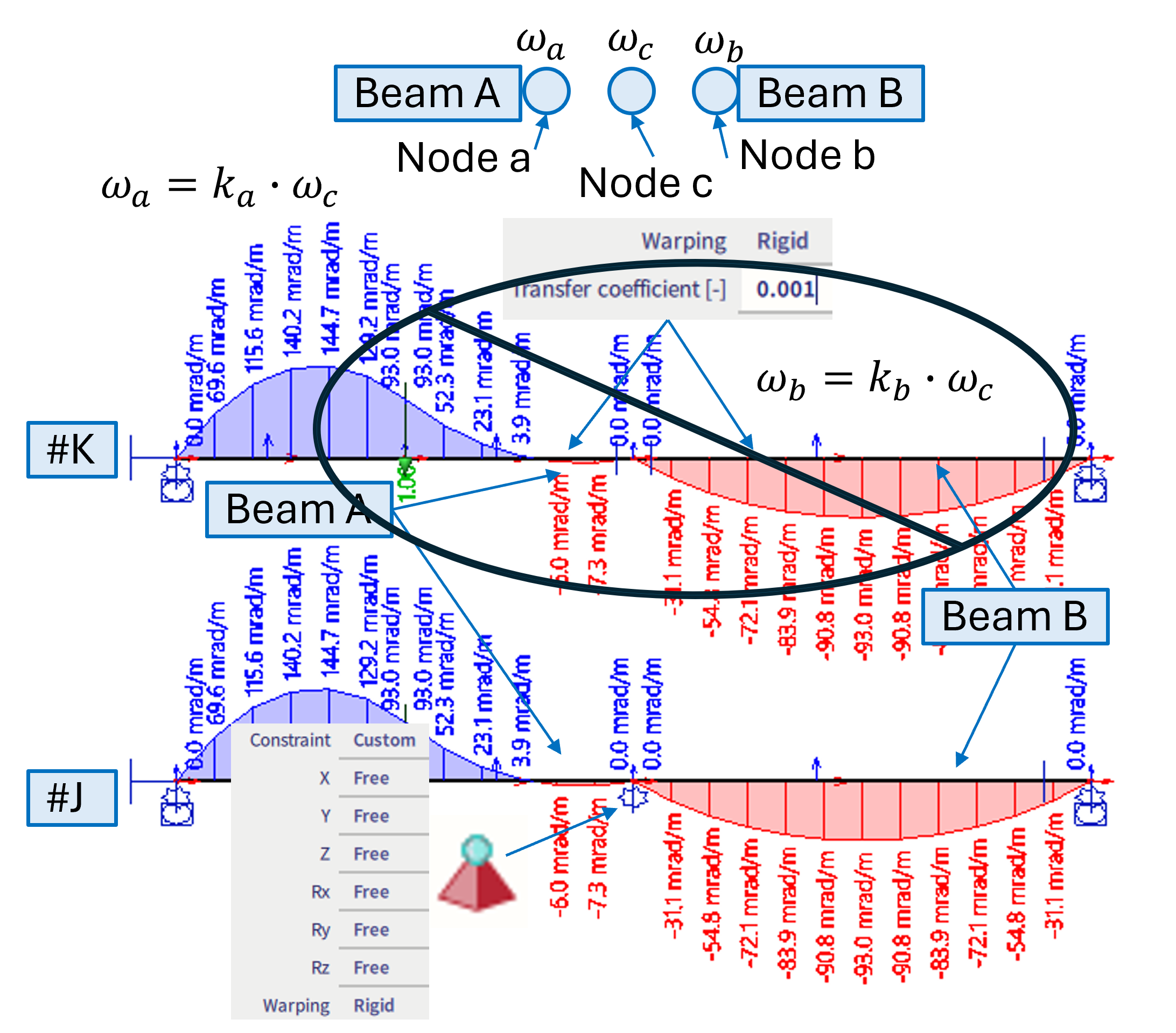
#K - It is not recommended to put the hinge on all the beams of one joint - In version 26.0 and 26.0 patch 1 this is causing issues. It is improved in 26.0 patch 2 (but still not recommended in general)
#J - in case the warping is desired to be 0 at both ends of beams of some joint, it is suitable to use the warping nodal support.
Note: When 7th DoF is activated, it is possible to define all 6 DoF (3 translation + 3 rotation) within a hinge as "rigid" and warping as "rigid" (with the transfer coefficient of 1) as well. This enables full warping transmission within such joint (along with full transition of the other DoFs). It is actually equivalent to case, where no hinge is modelled at all (all DoFs are transitioned, and warping with transfer coefficient of 1). However, in some cases the transfer of warping might be better described by a different transfer coefficient than 1 (depends on specific joint geometry, stiffeners, diagonals, etc.), what is the reason in general all 7 DoFs might be set to rigid.
C) Warping = Flexible
If this option is selected, additional stiffness parameter for this hinge is to be defined. Default value = 0.0 (hence referring to "Free" state of warping for this hinge). The unit of this stiffness is determined based on selected "Force" and "Length" units from the "Stiffness" chapter of the unit settings dialogue, and the dimension is "Force * Length ^3".
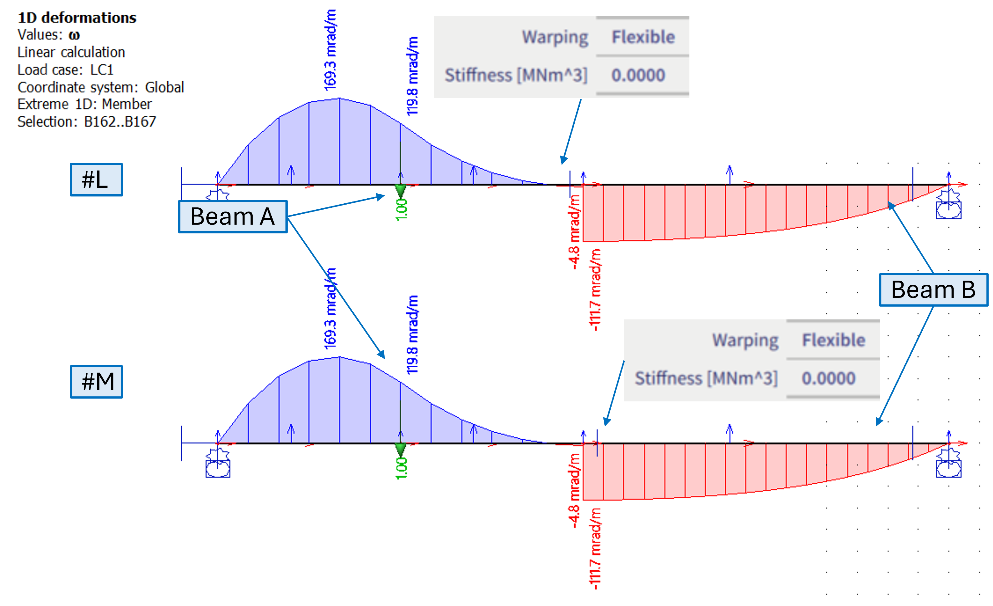
Alternatively to case #I , it is possible to use either warping = free, or flexible with 0 stiffness in order to avoid transition of the warping. In this case however, it does not depend on which beam such hinge is defined (depends on loading) - see cases #L and #M below.
#L - flexible hinge with 0 stiffness is on beam A (loaded beam)
#M - flexible hinge with 0 stiffness is on beam B (loaded is still beam A)
#L and #M are identical, and very similar to the case #I results
Note: Use warping = "flexible" with 0 stiffness as analogy to case, where all 6DoF are set to rigid and warping needs to be set to "free". Alternatively rigid with little coefficient defined on an appropriate end of beam is also possible.
Practical examples
Transfer coefficients on "L-shaped" column-beam frame connection
Based on structure discussed in literature [1], a numerical models of a simple L-frame structure were created in SCIA Engineer. Global geometry of the models is shown in the figure below. The structure is loaded by a torque moment - equivalent of 1kNm applied in the mid height of the column.
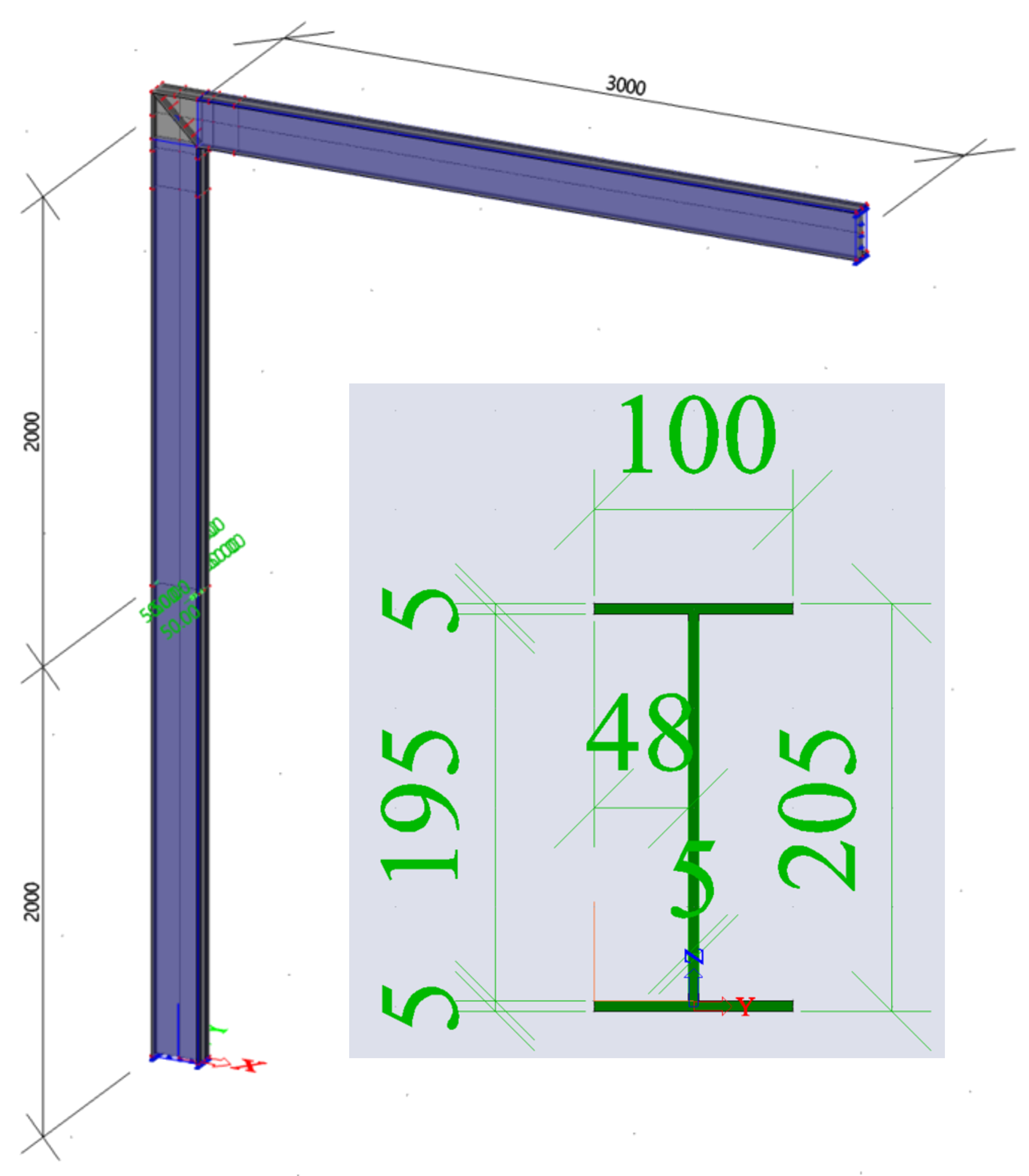
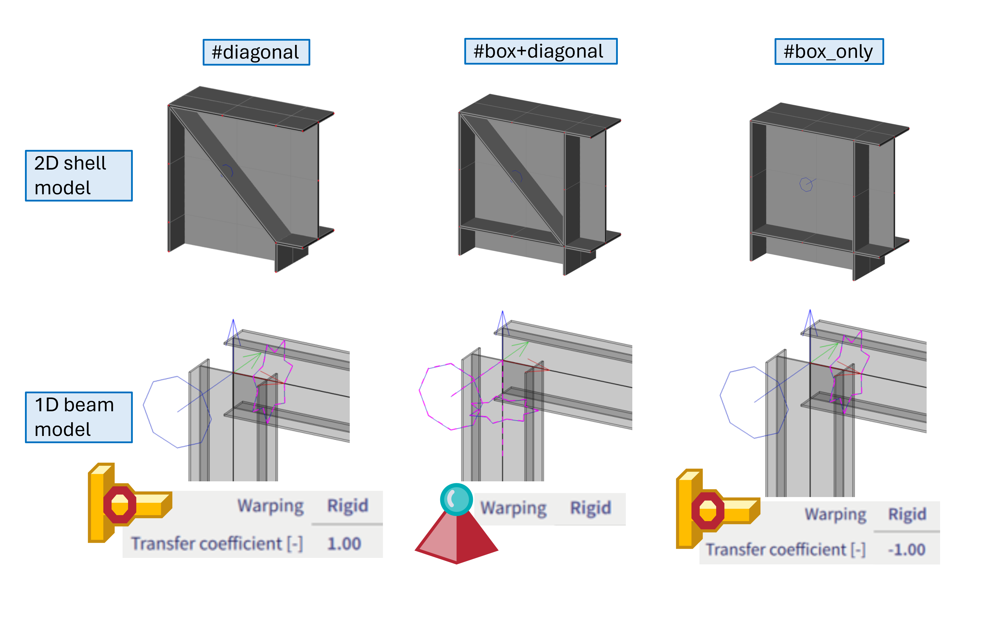
Several variants of 1D beam and 2D shell models are compared. Keeping the global geometry the same, these variants differ in the detail of the column-beam connection, as also shown in the figure below:
#diagonal = for 1D model variant, either no hinge at all might be considered, or alternatively hinge with transfer coefficient of 1 (if only the 7th DoF is released in this hinge, no matter whether such hinge is assigned to column head or horizontal beam).
#box+diagonal = for 1D model variant, this connection appears to be rather well described if the 7th DoF is constrained by the nodal support.
#box_only = for 1D model variant, hinge with transfer coefficient of -1 appears to yield quite a nice match between 1D and 2D model.
The rsults of the warping ω of these variants are compared in the figure below:
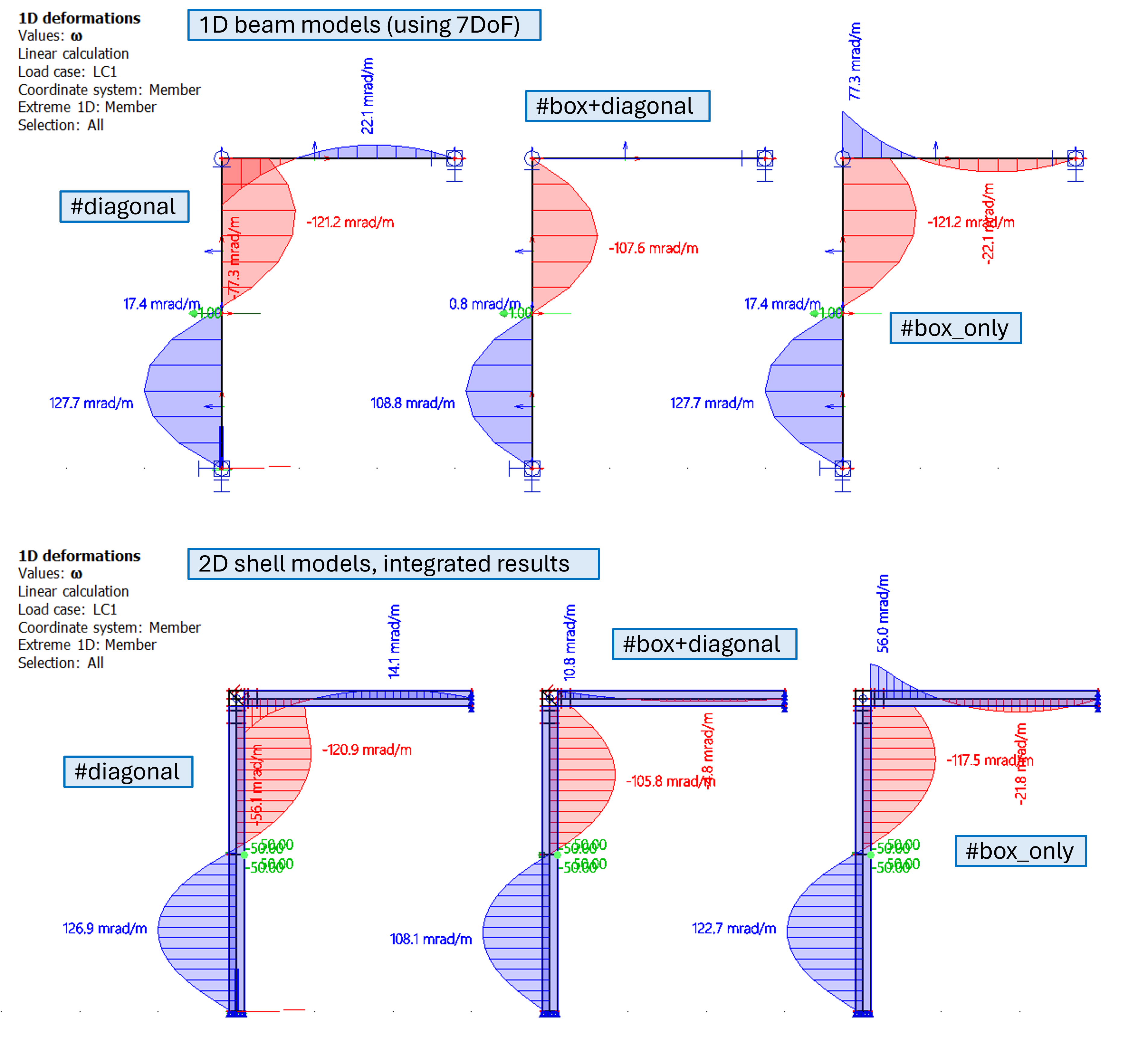
For the 2D shell model, the results of ω were numerically integrated using the integration member. This procedure is in general recommended if user is not sure how to set the transfer coefficients for a specific joint - to create separately more precise 2D shell model, load members by torque and use integration beam to determine what is the best match to consider such connection by 1D beam model.
Several cases of the #box+diagonal 1D beam model variant of the L-frame
Further, the variant #box+diagonal is investigated closely, several cases are compared:
#A = hinge is modelled in the column head, with transfer coefficient of -0.1
#B = this is the default variant of the #box+diagonal - hence, nodal support is applied
#C = the hinge is modelled in the horizontal beam, with transfer coefficient of -10
#D = the hinge is modelled in the horizontal beam, with transfer coefficient of -0.1
#E = the hinge is modelled in the horizontal beam, and is set to be "free" in warping (or analogically flexible with 0 stiffness)
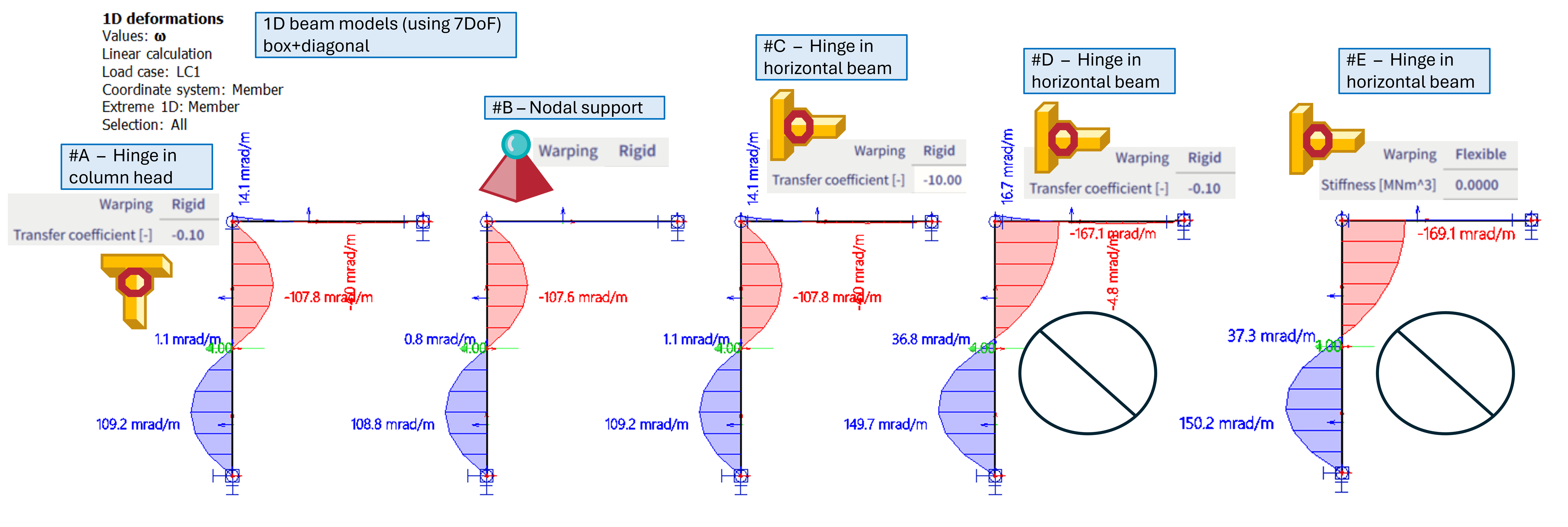
Discussion on the results:
It appears to be a little bit more precise to model this type of connection by suitably positioned hinge with transfer coefficient of -0.1 - see case #A (hinge in the column head), or case #C, where the inverse value is positioned on the hinge located on the horizontal beam.
However, these cases are a bit susceptible on correct position of such hinge with the transfer coefficient. For example, if the -0.1 transfer coefficient for hinge located on horizontal beam is modelled (case #D), instead of the column (case #A), the results are significantly different. Case #D is not yielding results similar enough to the 2D shell model.
Cases #D and #E are quite similar to each other, in case #D, only 1/10 of the warping from the column is being transferred into the horizontal beam, and case #E with free warping practically means no warping at all is being transferred in this connection. In case the transfer coefficient in case #D would be decreased further (to -0.001), the results would converge into the results of the case #E.
For this specific case of the #box+diagonal variant, the solution #B appears to be the most robust, considering the match of the results between 1D and 2D model, and ease of the input (no need to keep in mind whether to put proper hinge on column or horizontal beam). The connection is stiff enough (diagonal + box), so the warping deformation in such connection might be considered as 0 to simplify the case, hence fully constrained warping in the joint.
In general, it is assumed that in most cases, either rigid nodal support in warping, or hinge with warping = free, hinge with warping = rigid and transfer coefficient either 1 or -1 will be used. These settings always depends on the specific detail of the member connection (possibly applied load as well), and it is up to the user to do his own investigation, study corresponding literature, or create a comparative 2D model to determine how to model the hinges the most correctly for specific case.
Literature:
[1] Basaglia, C., Camotim, D. & Silvestre, N., 2012. Torsion warping transmission at thin-walled frame joints: Kinematics, modelling and structural response. Journal of Constructional Steel Research, 69(1), pp.39–53. https://doi.org/10.1016/j.jcsr.2011.07.016