![]()
|
||
|
|
||
The Shear Force Check is executed according to EN 1993-1-3 art. 6.1.5.
The shear resistance is calculated for each ‘web’ element separately and the cross-section resistance is taken as the sum of these element resistances.
Only elements with element types I, UO and SO are accounted for.
In addition, elements with stiffener type RUO or DEF are not accounted for.
Formula (6.8) is rewritten as follows for both directions:
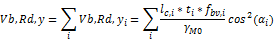
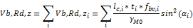
With:
αi = Angle of element i related to the principal y-y axis
lc,i = Centreline length of element i
By default the Shear Check is executed ‘without stiffening at the support’ In case Local Transverse Forces data are inputted which have the checkbox ‘No Local Transverse Forces Check’ activated, the Shear Check in those sections is executed ‘with stiffening at the support’.
The centreline length lc,i for each element i is taken from the Initial shape.
The angle αi for each element i is determined as the angle related to the principal y-y axis.
The relative web slenderness for each element i is determined according to formula (6.10a).
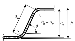
The slant height sw,i is taken as the notional width bp,i of the element under consideration as indicated on the following picture.
Special considerations are required for cross-sections with internal stiffeners (Type RI).
The following picture illustrates a web with internal stiffener:
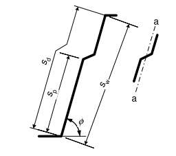
The internal stiffener and connected elements are seen as ‘one web’. This ‘composed’ web is seen as ‘one’ element i in the shear calculation.
For such a ‘composed’ web, the different distances are determined as follows:
The relative web slenderness is determined according to formula (6.10b).
The inertia of the stiffener(s) Is is taken from the Initial shape
The centreline length lc of this composed web is calculated as follows:
lc = sw + gr
With
gr = rm * [tan ( φ / 2) - sin ( φ / 2)]
If the first element is an outstand, gr is taken as gr at the end point of the last element.
If the last element is an outstand, gr is taken as gr at the starting point of the first element.
Reference is made to "Notional widths".
lc = sw + gr,first + gr,end
With
gr,first taken as gr at the starting point of the first element.
gr,end taken as gr at the end point of the last element.
The angle α of the ‘composed’ web concerns the angle of the centreline length lc relative to the principal y-y axis.
Neighbouring connected elements are seen as one ‘web’. A typical example of this is a sigma section: the web has two internal stiffeners which both are connected to the same internal element. As such they are recognized as forming one web.