![]()
|
||
|
|
||
Composite code checks are based on the Open Checks technology and SCIA Design Forms. However, in order to avoid duplicate input of some of the data and to take most advantage of the CAM, all input needed for composite checks have been centralized in the composite service in the Composite Beam Data member attribute and in the Composite setup.
This chapter gives detailed information about the settings available in the Composite setup and in the Composite Beam Data which are related to the composite checks.
Some general information about how to use the checks is also provided. Theoretical background about the content of the checks is not provided here. References to the appropriate code articles are usually provided in the detailed output of the checks themselves.
For more information about Open Checks and SCIA Design Forms, please refer to "Open Checks: Link with Scia Design Forms".
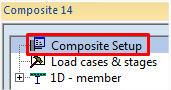
The composite setup is accessible from the composite service tree.
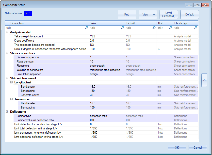
The settings related to the analysis model (CAM) have been detailed already in the previous chapter "Spřažený výpočtový model ve SCIA Engineer". The rest of the settings are related to the composite checks. Most of them define default settings to be used for composite members without specific settings. Those settings can be overriden (marked overridable in the table below) by means of Composite Beam Data attributes (see next chapter "Composite Beam Data").
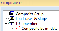
The composite beam data is accessible from the composite service tree. It can be added to any composite beam.
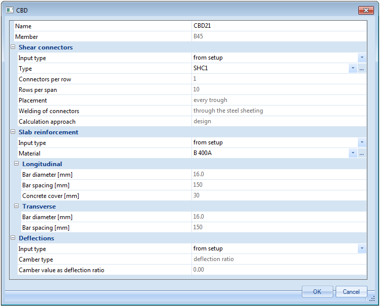
The composite beam data attribute allows to override for a specific composite beam the default settings defined in the composite setup. For each group of settings (e.g. shear connectors or slab reinforcement) it is possible to separately specify if the default settings must be used or rather some customized values.
Most of the composite beam data settings get their default value from the composite setup. A few exceptions exist, which are mentioned in the table below.
| Name | name of the composite beam data attribute |
| Member | read-only; name of the related composite beam |
| Shear connectors | |
| Input type |
override setting
|
| Type |
type of shear connectors, selected from the shear connectors library (see below "Shear connectors library") There is no default value for this setting in the composite setup. The default is taken as the first shear connector type available in the shear connectors library. This applies for composite beams without composite beam data. |
| Connectors per row |
number of connectors per row (perpendicularly to the axis of the beam) |
| Rows per span |
total number of rows of connectors in one span; used in case the corrugation of the sheeting is parallel to the beam only EN1994 |
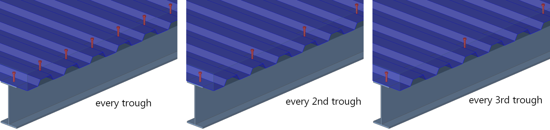
| Placement |
used in case the corrugation of the sheeting is perpendicular to the beam only EN1994 |
| Number of rows (between points of min & max moment) |
number of rows of connectors between the points of min and max moments in one span only AISC |
| Welding of connectors |
method of welding of the shear connectors
|
| Calculation approach |
approach for the calculation of the connectors
|
| Slab reinforcement | |
| Input type |
override setting
|
| Material |
reinforcement steel material for the slab reinforcement There is no default value for this setting in the composite setup. The default is taken as the default reinforcement steel material from project settings (EC-EN) or as the first available reinforcement steel material in the library of materials. This applies for composite beams without composite beam data. |
| Longitudinal |
Bar diameter, bar spacing and concrete cover of reinforcement bars in the slab parallel to the beam |
| Transversal |
Bar diameter and bar spacing of reinforcement bars in the slab perpendicular to the beam |
| Deflections | |
| Input type |
override setting
|
| Camber type |
type of definition of the camber value
|
| Camber value |
camber value for type absolute, defined as a fixed length |
| Camber value L/x |
camber value for type relative, defined as a ratio of the span length, e.g. L/200 |
| Camber value as deflection ratio |
camber value for type deflection ratio, defined as a ratio of the permanent deflection |
The composite shear connectors library is accessible as any standard library, from the Libraries menu (composite sub-menu), from the main tree view (Libraries>Composite branch) and from the composite beam data attribute, when assigning shear connectors to a composite beam (see above "Composite Beam Data"). A selection of pre-defined shear connectors is available in the system library ( ).
).
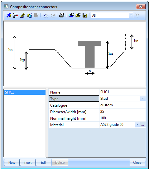
| Name |
name of the shear connector type |
| Type |
generic type of connector; possible values are Stud, Hilti, Channel and Bar hoop |
| Catalogue | catalogue designation, can be any text, keyword... may be used for filtering the library (using the catalogue filter). Typical use would be the name of the manufacturer or the name of the product range |
| Diameter/width | cross-sectional dimension of the connector; typically diameter of a stud |
| Nominal height | nominal height of the connector for the calculation of the resistance |
| Material | steel material of the connector |
All settings above are transmitted to the composite checks. They do not affect the analysis model.
All composite checks are accessible from the composite service tree. They are displayed after a successful analysis of the structure (analysis results available).
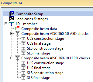
All composite checks use the same standard settings as other result services in SCIA Engineer. Results are available as text and graphical output. The text output can be obtained in a summary table output (only main results, one row per result) or as detailed output (full details of check, with intermediate results…).
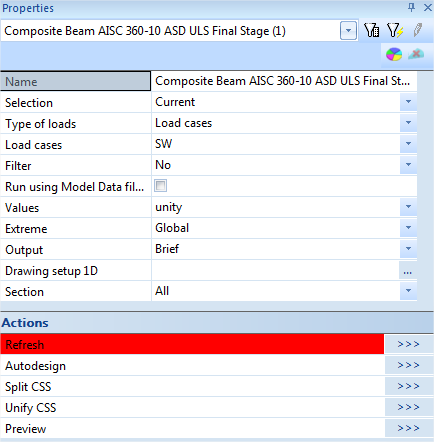
| Name | name of the selected check |
| Selection | selection of entities on which the check will be performed (all, current, advanced, named selection, design group) |
| Type of loads | type of actions to be used for the check (load case, combination, result class) |
| Load case | selected load case for the check (in case type of loads = load case) |
| Combination | selected load case combination for the check (in case type of loads = combination) |
| Class | selected result class for the check (in case type of loads = class) |
| Combinator strategy |
strategy used for handling envelopes
|
| Filter | standard filter on members (wildcard, cross-section, material, layer) |
| Print combination key | when enabled, print the combination key along with the results in the text output |
| Values | selection of the value(s) for graphical representation |
| Extreme | extreme selection mode (section, local, member, interval, cross-section, global) |
| Output |
text output format
|
| Drawing setup 1D | detailed configuration of graphical output |
| Section | sections for which the check must be performed on each selected member (all, ends, inputted, inputted+ends) |
| Refresh >>> | action button: perform the check |
| Autodesign >>> | action button: autodesign according to selected settings; filter must be cross-section (see more detailed explanation in Autodesign manual "AutoDesign - globální optimalizace") |
| Split CSS >>> | action button: split cross-section optimization according to unity check value of selected members |
| Unify CSS >>> | action button: assign the same cross-section to several members having different cross-sections |
| Preview >>> | action button: display the text output window |