![]()
|
||
|
|
||
The check of prestressed concrete is performed only according to EN 1992-1-1. There are not any implementation of special check according to EN 1992-2 which is code for design of bridges. There is only possible to used special TDA calculation according that code (see "Construction stage analysis (TDA EN 1992-2)").
The final concrete setup is synthesis of national dependent values and standard setup independent values.
Code dependent values are possible to see in Project Data > Code > National annexes.
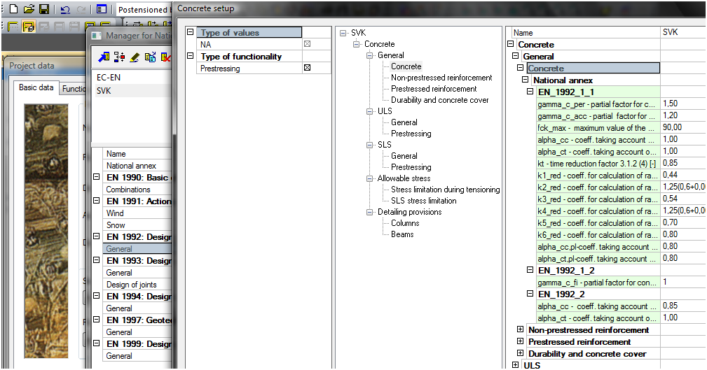
Code independent values are possible to see in Libraries > Concrete setup.
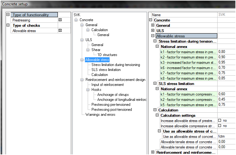
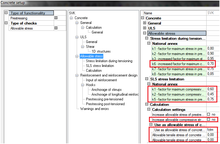
Complete setup is visible in appropriate concrete check filtered according to check. For instance see concrete setup for Allowable stresses of concrete.
Some important settings from concrete setup will be explained in the following chapters
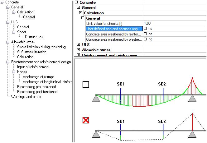
This functionality is suitable for fast performing of concrete checks only in user defined section, where is supposed the most loaded structure and extreme results. Check is performed only in those user defined d section and duration of check is shorter. It is available for all concrete checks and design.
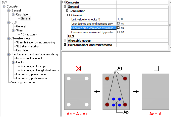
When this check box is switch ON, then area of concrete CSS is reduced by bars. It has effects on all concrete 1D checks.
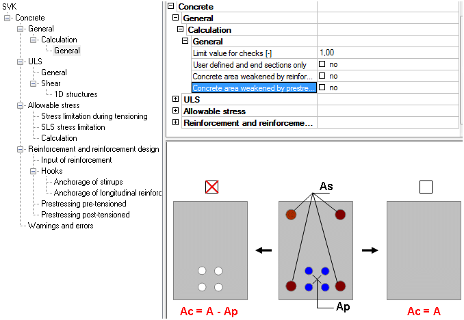
When this check box is switch ON, then area of concrete CSS is reduced by bars. It has effects on all concrete 1D checks.
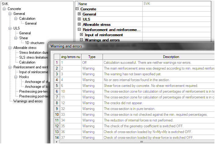
When some check is performed then warning or error can be printed in the table.
All warnings and errors are stored in the concrete setup.
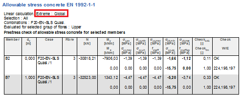
The modelled structure can be checked by two ways:
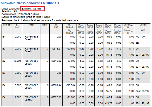
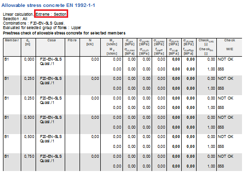
Member check is performed from the standard concrete check service. The results are displayed along the selected members. The output table has different output according to extreme:
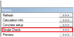
Almost all concrete checks has single check. It is detailed analysis of one cross-section. Action button to go there is following in the bottom of service.
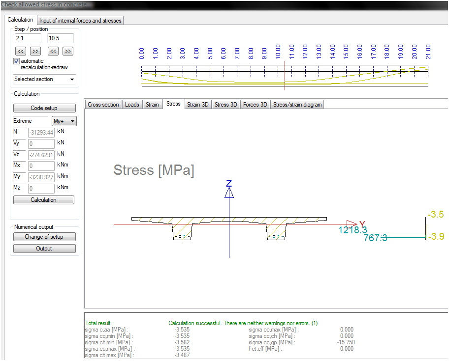
Dialogue of single check provided to user selects:
Extreme of normal forces (N+; N-; Vz+; Vz-...)
Section along the selected member
Appropriate tabsheet with detailed results. Tabsheets are dependent on type of concrete service, but mainly there are following:
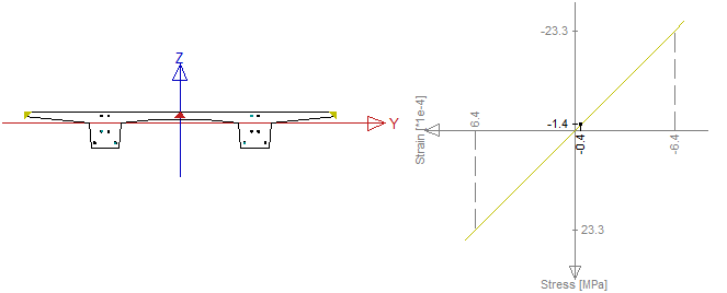
Cross-section
Loads
Strain
Stress
Stress/strain diagram
Definition of named items was described in chapter "Library of Named items". Here the using in concrete checks will be explained. The idea of using named part is to get user friendly results and to increase speed of check. SCIA Engineer supports following named items in the following services.
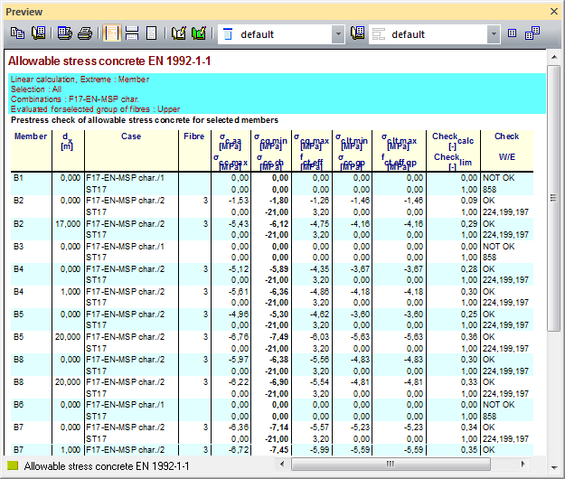
Named fibres
Check response
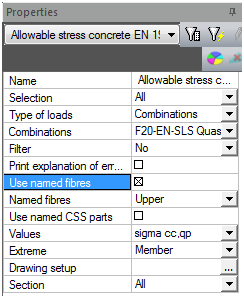
Allowable stresses of concrete
Named cuts
Allowable principal stresses
Named joints
Check response – check of shear in construction joint
Design As
Named parts of CSS
Check response
Allowable stresses of concrete
Allowable principal stresses
For instance you can see results of allowable concrete stress for upper fibres
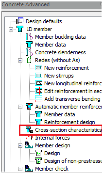
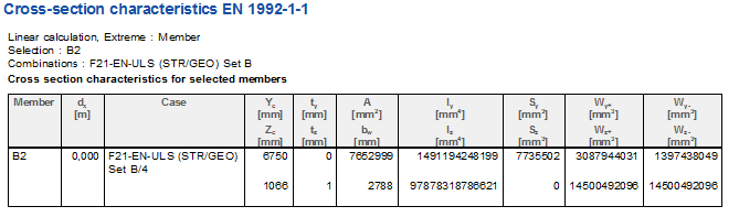
The service of CSS characteristic is service which can provide to user all necessary information about the CSS. This service is situated in Concrete Advanced > 1D member.
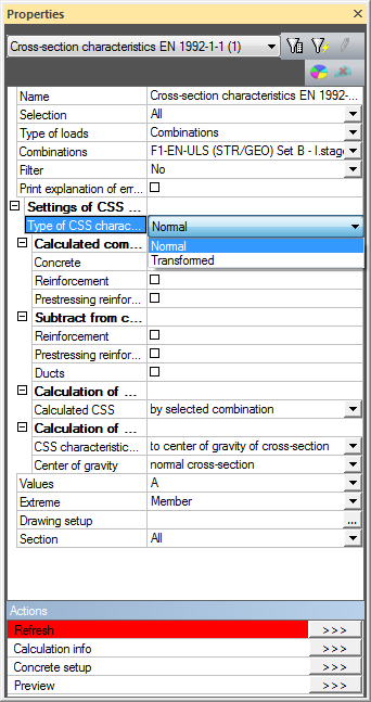
This service performs calculation of geometrical properties of cross-section with including the following:
the values for normal characteristic A, Iy, Iz,ty,tz,Sy,Sz,bw, Wy+, Wy-, Wz+, Wz-, iy, iz
the values for transformed characteristic Ai, Iyi, Izi,tyi,tzi,Syi,Szi; Wyi+, Wyi-, Wzi+, Wzi-, iyi, izi
The results can be following:
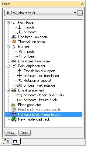
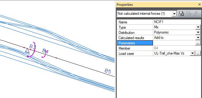
The frame XZ which is used for the time dependent analysis doesn’t respect effects of torsion in this project. The envelopes of mobile loads for extreme Mx (torsion moment) should be analysed on different project type frame XYZ. The value of Mx should be defined in project Frame XZ as Not calculated internal force.
The user should defined not calculated internal forces in menu Loads > Not calculated internal forces for selected load case.
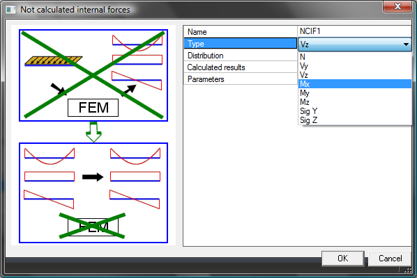
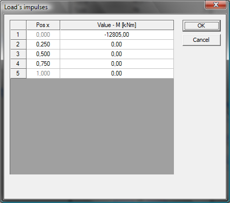
The dialog for definition of Not calculated internal forces is following. There are several types. We use type Mx.
Distribution should be following; type Polynomic is used for definition only in one section near the second support.
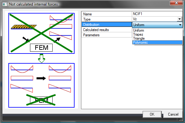
The value of Mx is defined in this dialog.
The displaying of not calculated internal forces in 3D window is following
The cracks of the prestressed members are calculated according to chapter 7.3 from EN 1992-1-1 and check is performed in service Concrete Advanced > Member check > check of prestressed concrete > Crack control. The prestressed structure is with bonded tendons and will be checked for frequent combination according to table 7.1N from EN 1992-1-1. The exposure class is set in chapter "Exposure class" as XD3. The decompression has to be checked in this case.
The explanation of displayed values is following
The stress before and after anchoring
 (5.42)
Stress from SLS combination
 (7.2.(2))
 (7.2.(3))
Other not checked, only drawn
σp,inc – increment of stress from selected LC
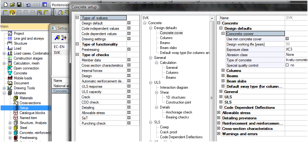
Some important values needed for calculation is recommended to set before check is performed.
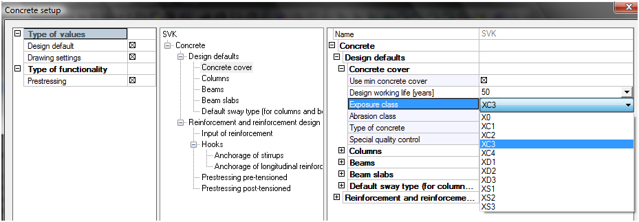
The exposure class of concrete is possible to set in Concrete setup > Design defaults. The check of allowable concrete stresses and crack width depends on this exposure class. The class XD3 is set in this example.
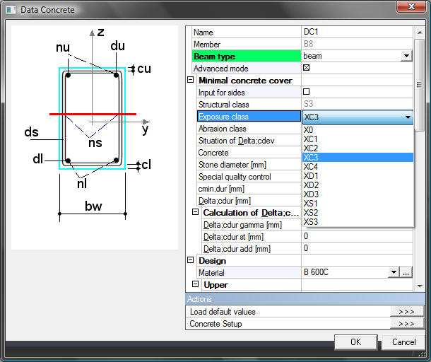
The exposure class for each member is also possible to set by Member data.
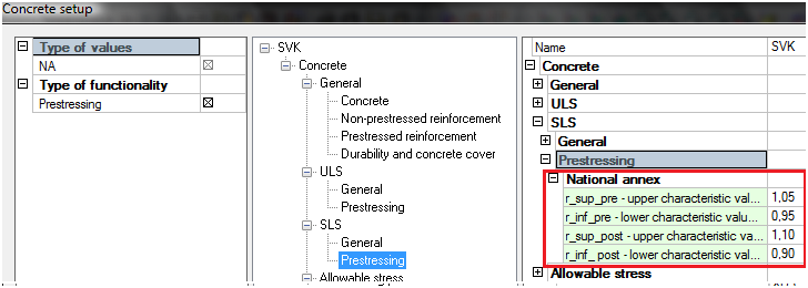
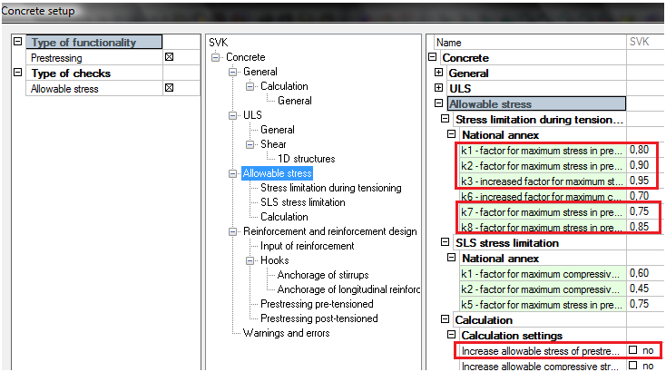
The upper and lower factors of prestressing force for check of allowable concrete stresses are possible to set in Concrete setup > SLS > Prestressing.
The factors for the calculation of limit values of concrete stresses from the code EN 1992-1-1 is possible to set in Concrete setup > Allowable stresses.
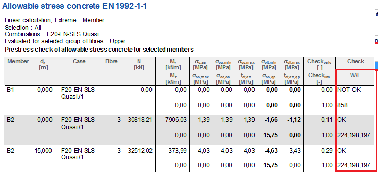
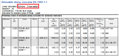
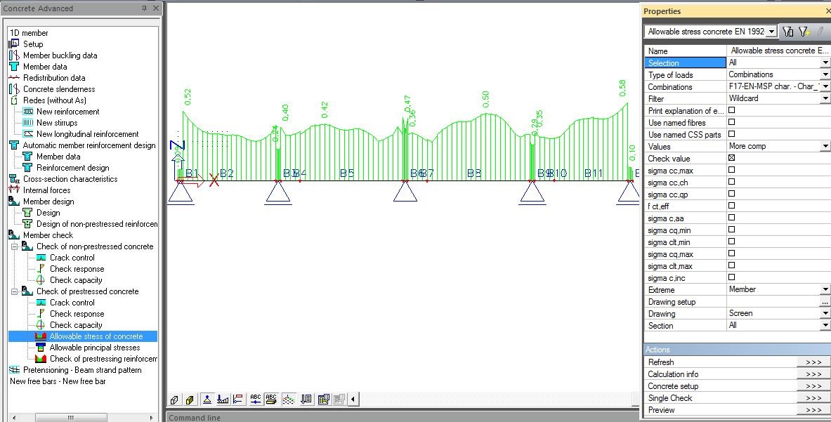
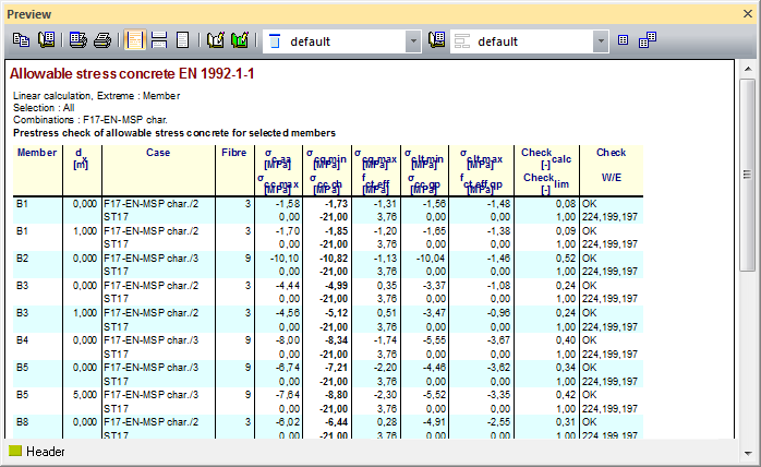
The user has possibility to perform this check in Concrete Advanced > Member check > Check of prestressed concrete > Allowable concrete stresses. The results of the check will be calculated and drawn for selected combination and value. For instance Check value of the SLS characteristic combination in 100 years is following.
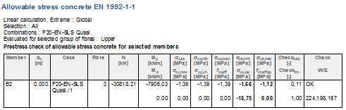
The output table with extreme Member is following.
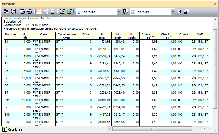
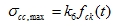
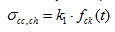
For the selected values σcc,ch and σcq,min are results following
and output table is following
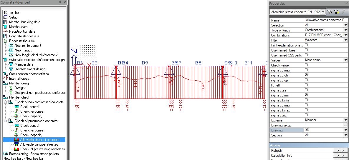
The concrete stress should be calculated for selected fibre only
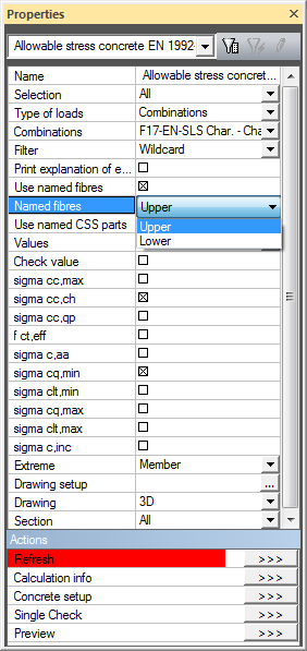
Then results for upper fibres are following
The detailed analysis only in one section is possible using button Single check
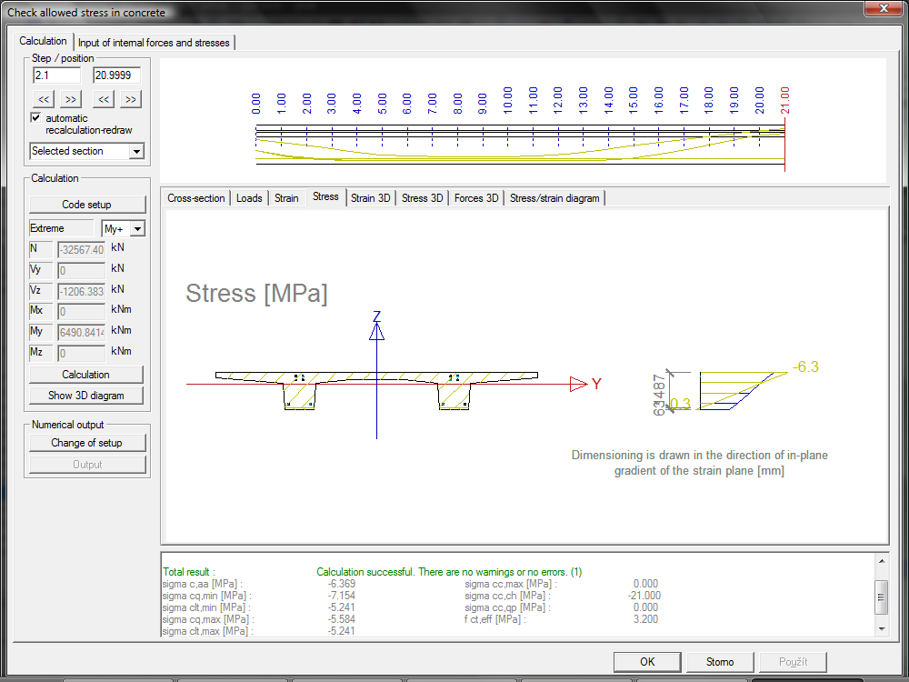
The explanation of displayed values is following
The stress before anchoring
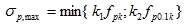 (5.41)
The stress after anchoring
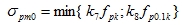 (5.43)
The crack limitation from SLS characteristic combination during service – cracks and deformation
 (7.2(5))
Others not checked stresses, only drawn
The factors for the calculation of limit values of concrete stresses from the code EN 1992-1-1 is possible to set in Concrete setup > Allowable stresses.
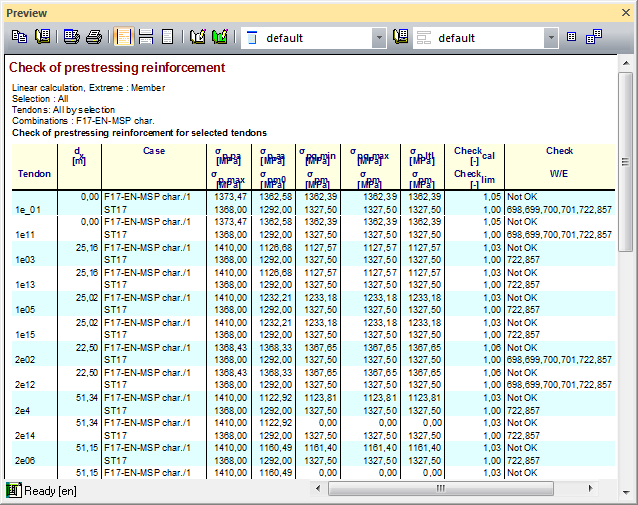
The user has possibility to perform this check in Concrete Advanced > Member check > Check of prestressed concrete > Check of prestressing reinforcement. The results of the check will be calculated and drawn for selected combination and value. For instance Check value of the SLS characteristic combination in 100 years is following.
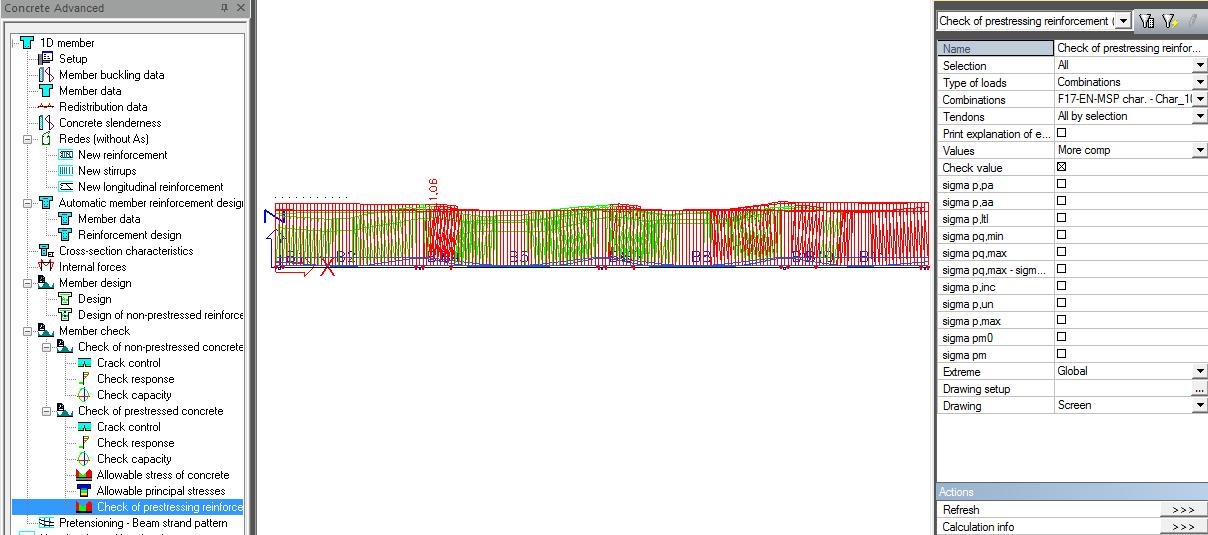
The output table with extreme Member is following.
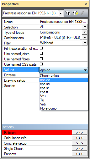
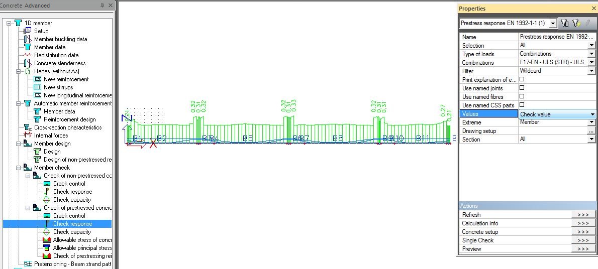
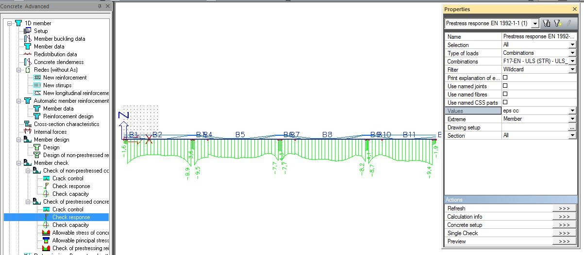
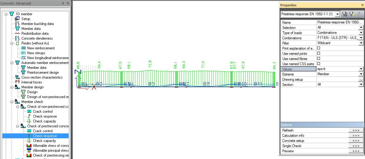
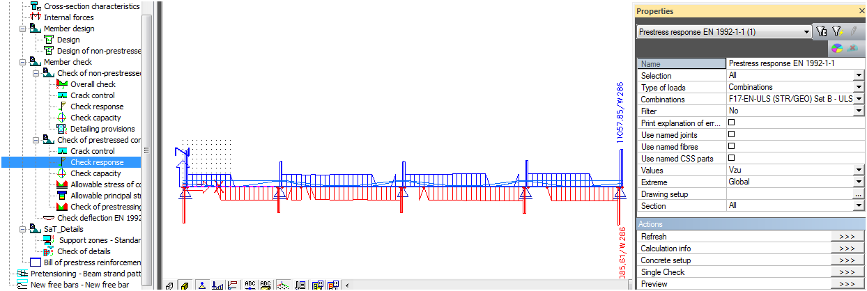
The CSS response on acting combination is calculated in this check. The check is in Concrete Advanced > Member check > Check of prestressed concrete > Check response. The results of the check will be calculated and drawn for selected combination and value. There are following values for selection
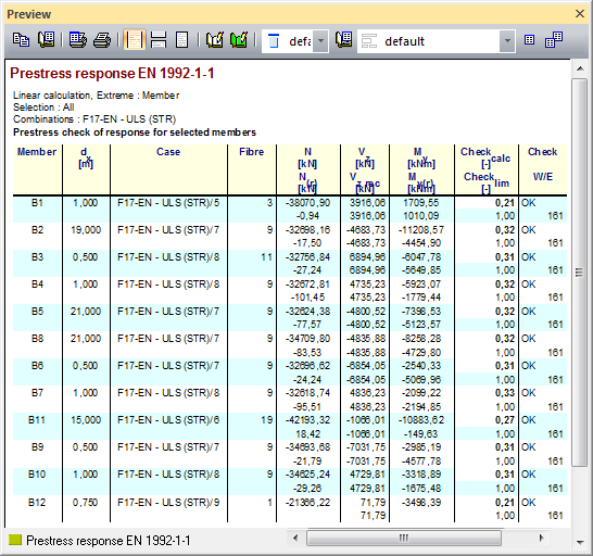
The results are calculated and drawn for F17-EN-ULS(STR) - check value.
The output table with extreme Member is following.
The strain in concrete under compression for F17-EN-ULS(STR) – eps_cc.
The strain in tendons under tension for F17-EN-ULS(STR) – eps_tt.
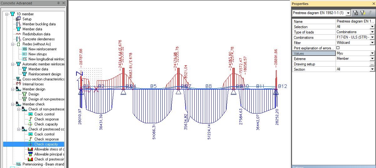
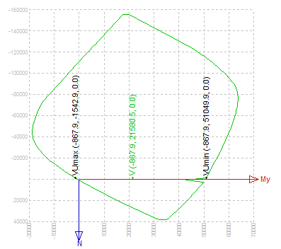
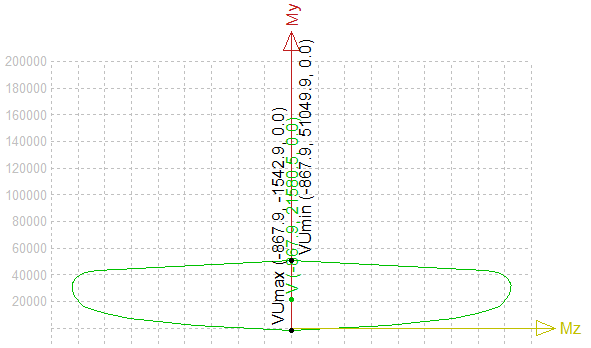
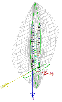
The resistance of CSS acting by combination of moment and normal force is calculated using interaction diagram in this check. The check is in Concrete Advanced > Member check > Check of prestressed concrete > Check capacity. The default setup options are following:
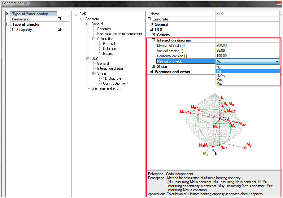
The recommended type of interaction diagram is following:
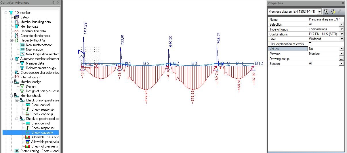
The results of the check will be calculated and drawn for selected combination and value. There are following values for selection
The moment capacity in direction y for F17-EN-ULS(STR) – Myu
The axial capacity for F17-EN-ULS(STR) – Nu
The output table for F17-EN-ULS(STR)
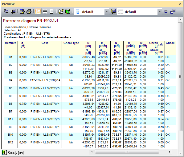
The results aim single checks are following:
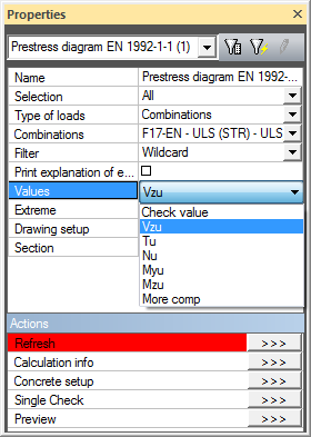
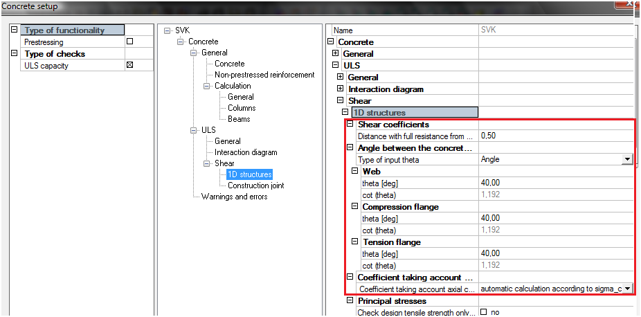
The shear check is performed in Check response and check capacity as value Vzu in property. At the beginning the existing of cracks in ULS is calculated:
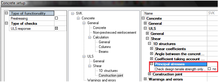
The parameters for the calculation of shear check is possible to set in Concrete setup > ULS > Shear.
The shear check for F17-EN-ULS(STR) – Vzu.
The output table with extreme Member is following.
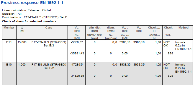
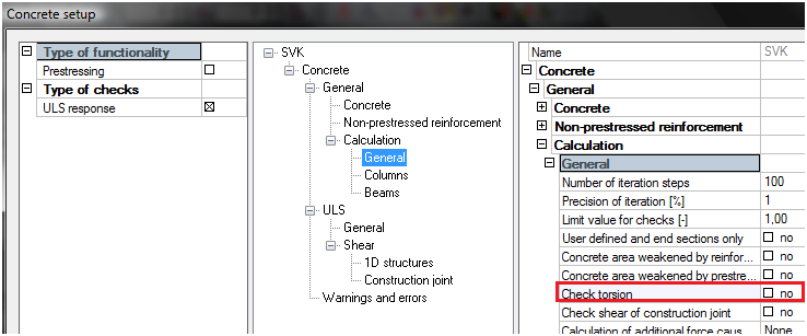
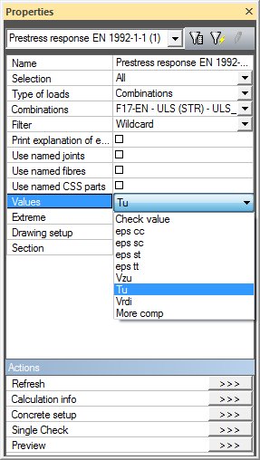
The torsion check is performed in Check response and check capacity as value Tu in property. The calculation is performed according to chapter 6.4. The check of torsion is required if check box in Concrete setup > General is turned ON.
The shear check for F17-EN-ULS(STR) – Tu.
The torsion is checked only if stirrups are defined on the beams, when the stirrups are not defined check of allowable principal stresses is required
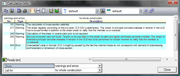
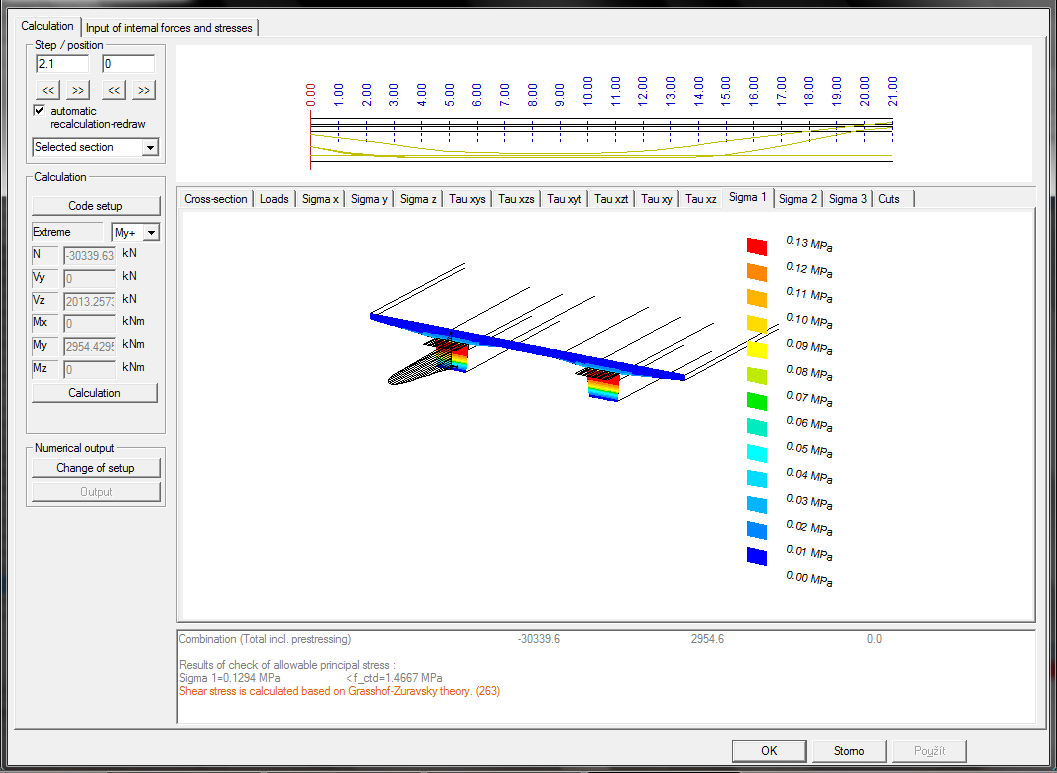
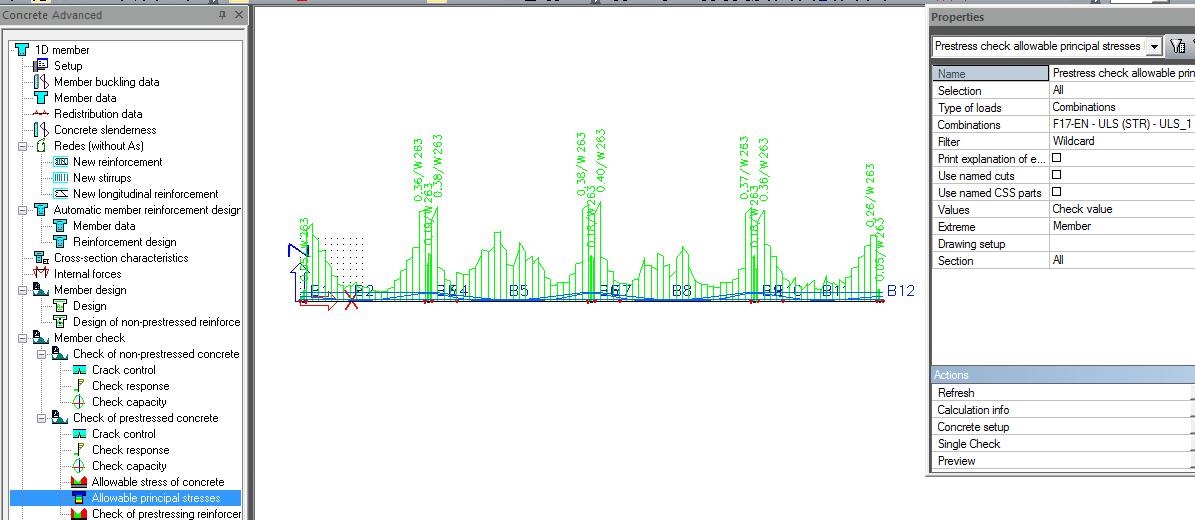
The check of allowable principal stresses in tension in ULS is performed for verification that CSS is uncracked CSS under acting load. This check is available in Concrete Advanced > Member check > Check of prestressed concrete > Allowable principal stresses. When the check of tensile stress is required only in compression zone then check box Concrete setup > ULS > Shear has to be checked. The principal stresses are calculated in predefined cuts by user (see "Named cuts").
The service of allowable principal stresses has the property dialog with following values
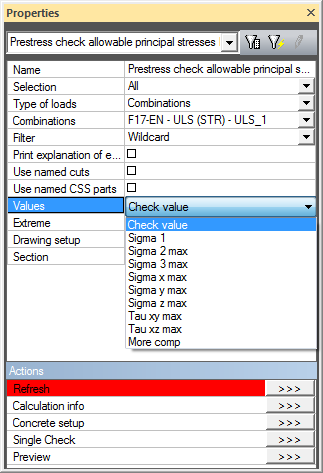
The check value for F17-EN-ULS(STR) is following.
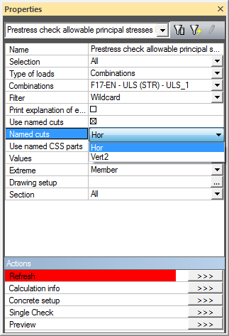
There is possibility to checked only selected named cuts or part of CSS in this service.
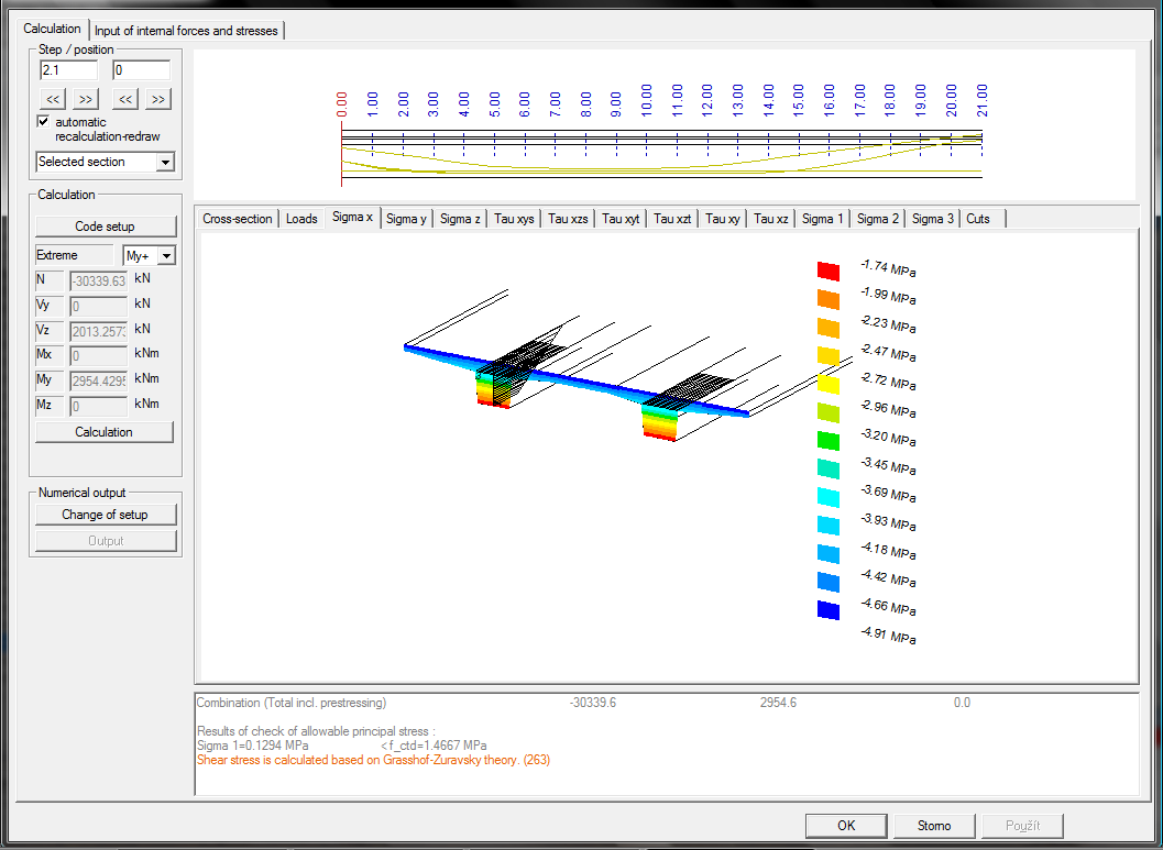
The user has the possibility to see detailed results in selected section along the beam using the button Single check. The stress σx for F17-EN-ULS(STR) is following.
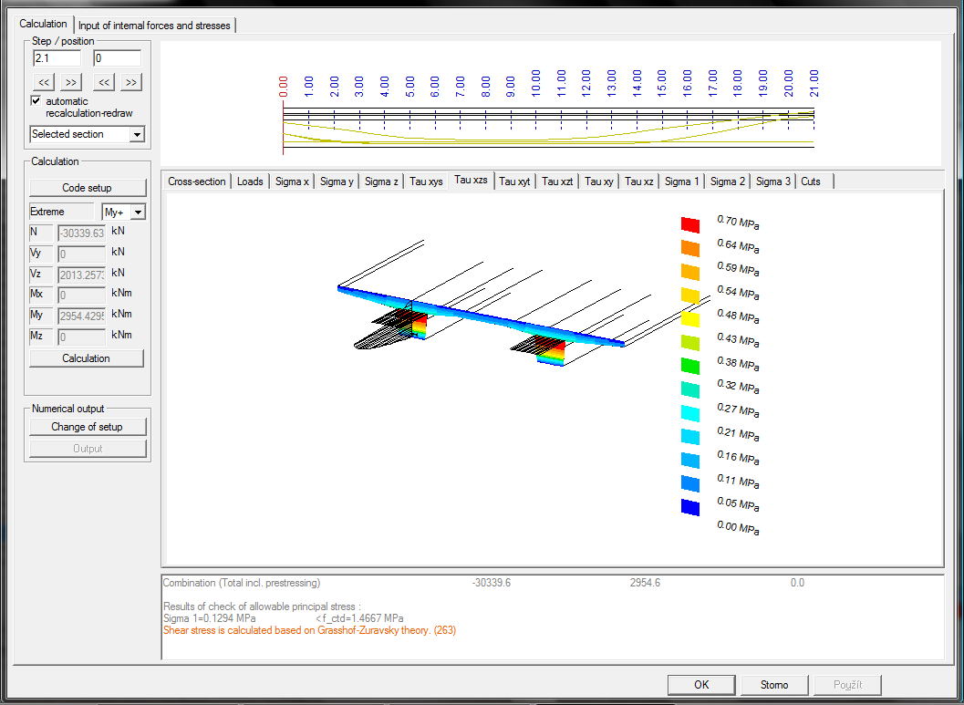
The stress τxz for F17-EN-ULS(STR) is following
The principal stress σ1 for F17-EN-ULS(STR) is following