![]()
|
||
|
|
||
In this paragraph the basic principle of the plastic property calculation is explained.
The principle is illustrated for a general cross-section made out of one material which has equal characteristics in both tension and compression (like for example Steel).
As shown on the following picture, this cross-section is loaded by a bending moment M which causes part of the cross-section to be in compression (C) and part of the cross-section to be in tension (T).
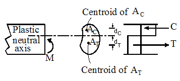
All the fibres in this cross-section have yielded as shown by the stress blocks.
The Plastic Neutral Axis (PNA) is defined by the axis located between the fibres yielding in compression and those yielding in tension. This axis is off course parallel to the principal axis about which the moment was applied.
For a single material cross-section with homogeneous material characteristics the PNA is easily determined as the axis which splits the cross section into two equal areas: the area AC in compression and AT in tension.
The Plastic Section Modulus Wpl is calculated as the sum of the First Moments of Area of the part in tension (ST) and the part in compression (SC):

with:
|
AC and AT |
The areas of the section in compression and tension respectively for a bending moment about the given principal axis.
|
|
dC and dT |
The distances from the centroid of the areas of the section in compression and tension respectively to the Plastic Neutral Axis, measured perpendicular to the given principal axis. |
Using the material strength f of the homogeneous material the Plastic Moment Mpl is calculated as follows:

The basic principle explained in the previous paragraph holds true for a homogeneous uni-strength material. In general however there are several complexities which need to be accounted for:
Consider the following composite section as an example:
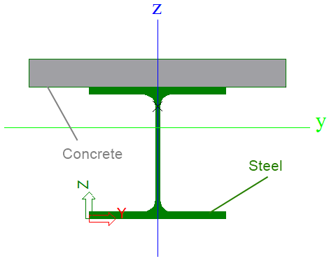
For a positive My bending moment about the principal axis, the concrete will be in compression while the steel will be in tension.
In case of a negative My bending moment about the principal axis, the concrete will be in tension while the steel will be in compression.
Depending on the position of the Plastic Neutral Axis one of the materials can even be partially in compression and partially in tension.
The calculation of the Plastic Moment is therefore split according to axis and according to sign which leads to Mply+, Mply-, Mplz+ and Mplz-. For each of these plastic magnitudes a separate calculation is done.
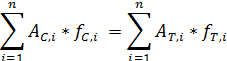
The determination of the Plastic Neutral Axis needs to take into account the material characteristic of each part. In general the following equation is solved which specifies an equilibrium of tensile and compressive forces:
with:
|
n |
The number of cross-section parts |
|
AC,i |
The area in compression of part i |
|
fC,i |
The compressive strength of part i |
|
AT,i |
The area in tension of part i |
|
fT,i |
The tensile strength of part i |
With the position of the PNA known, the Plastic Moment can be determined as follows:
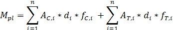
In which di signifies the distance from the centroid of the area of part i of the section to the plastic neutral axis, measured perpendicular to the given principal axis.
The above Plastic Moment calculation assumes a 'full bond' between the different materials. The actual Composite checks take into account the effects of partial bond and recalculate the Plastic Moments accordingly.
Since for each part the material strength can be different there is no more straightforward way to obtain the Plastic Section Modulus Wpl. Within SCIA Engineer, this value is referenced to the material of the 'first' inputted polygon, see also the paragraph on "Extension: Multi-Material (Composite) sections".
In addition, since there is both a positive and a negative Plastic Moment for the given axis, the final Plastic Section Modulus is determined using the minimum of both.
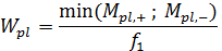
With f1 the material strength of the 'first' polygon. This can either be the compressive or tensile strength of this material depending on which stress dominates in this part.
These values for the Plastic Section Moduli are merely used for display in the Cross-Section Manager. The actual Composite checks directly use the Plastic Moments which are thus not referenced to the 'first' material but take into account all material characteristics.
As indicated in the above paragraphs the plastic calculation requires the compressive and tensile strength of the respective material. These values are defined as follows for materials with code dependent data:
|
Material |
Compressive strength fC |
Tensile strength fT |
|---|---|---|
|
Steel |
fy |
fy |
|
Aluminium |
fy |
fy |
|
Concrete |
fck |
Taken as zero |
|
Masonry |
fck |
Taken as zero |
|
Timber |
fc,0,k |
ft,0,k |
|
Other |
240 N/mm^2 |
240 N/mm^2 |
Any material which does not have code dependent data is taken as 'Other'.