Composite Beam Analysis Model - Theoretical background
This chapter gives a detailed description of the calculation of the stiffness of a composite beam in the context of the Composite Analysis Model in SCIA Engineer. For an overview, see the chapter related to the Composite Analysis Model.
General principles
As mentioned in the overview chapter, several approaches are available for the analysis model of a composite floor.
Deck as a diaphragm and beams with transformed composite cross-section
This is the conventional approach. It is intuitive and computationally cost-effective. It produces analysis and design results close to hand calculation techniques. It is usually suitable for the design of standard composite floors.
In SCIA Engineer, this approach is proposed by default. Composite decks are set by default to be analyzed as rigid diaphragms. Metal decks are set by default to be analyzed as flexible diaphragms. Composite beams are set by default to be analyzed with Standard composite action - i.e. using transformed cross-section method.
Deck as standard FEM plate and beams with transformed composite cross-section
This technique uses transformed cross-sections for composite beams, in a similar way as the previous approach. However, the real stiffness of the deck is taken into account in the analysis model, which allows to take into account interactions in the system that are due to the contribution of the deck. It is recommended for the design of complex composite floors, especially when irregularities in the supporting system might induce unusual interactions and redistributions of internal forces between beams via the deck.
In SCIA Engineer, this approach may be obtained by setting the Element behaviour of a composite/metal deck to Standard FEM. Composite beams should use Standard composite action.
Deck as standard FEM plate and beams modelled as eccentric plate ribs
In this case, the composite beams are modelled with their real eccentricity, without assuming a participating width to estimate the stiffness of the composite cross-sections. The shear lag effect is evaluated directly by the FEM analysis model. This approach is recommended for complex structures where effective widths cannot be estimated safely. It is also ideal for advanced analysis, such as footfall analysis.
In SCIA Engineer, this approach is obtained by setting the Element behaviour of a composite/metal deck to Standard FEM and using Advanced composite action for the composite beams.
Degree of composite action
First let us consider two boundary cases: a composite beam with full composite action and a composite beam without composite action (i.e. without shear connectors).
For a beam with full composite action, the properties of the transformed composite cross-section can be evaluated by the conventional approach, using the actual geometry of the composite cross-section and taking into account the different values of E-modulus for steel and concrete. The cross-section is considered as monolithic, i.e. without any slipping between the steel and concrete parts.
For a beam without composite action, the lever arm effect disappears completely because of the absence of connectors. Therefore, no axial force can be developed, neither in the steel beam nor in the concrete deck. The moment of inertia of the composite cross-section can thus be estimated by just summing the own inertia of the steel beam and that of the participating width of the concrete deck. As it is common to assume that the bending stiffness of the deck is negligible, usually only the moment of inertia of the steel beam is considered in that case.
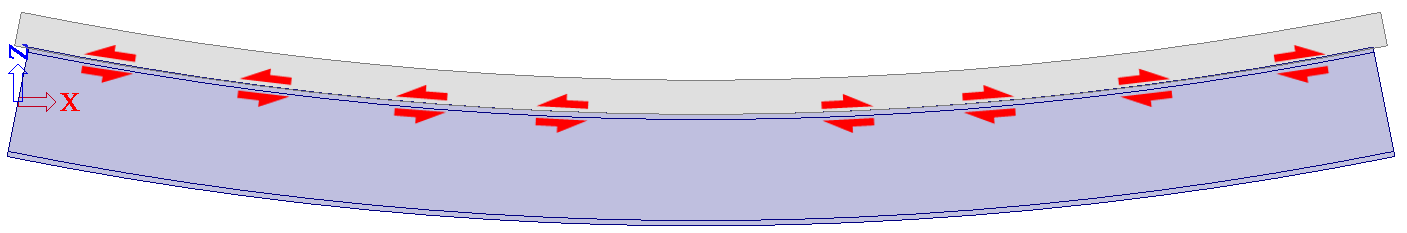
Taking into account a partial composite action may be estimated by means of an intermediate stiffness value for the composite beam. The slip between the steel beam and the concrete deck due to the flexibility of the shear connection leads to a reduction of the axial forces transmitted to the beam and to the deck. That reduction may be simulated by a reduction of the lever arm of the parts of the cross-section. This is obtained by interpolating between the boundary stiffness values described in the previous paragraphs.
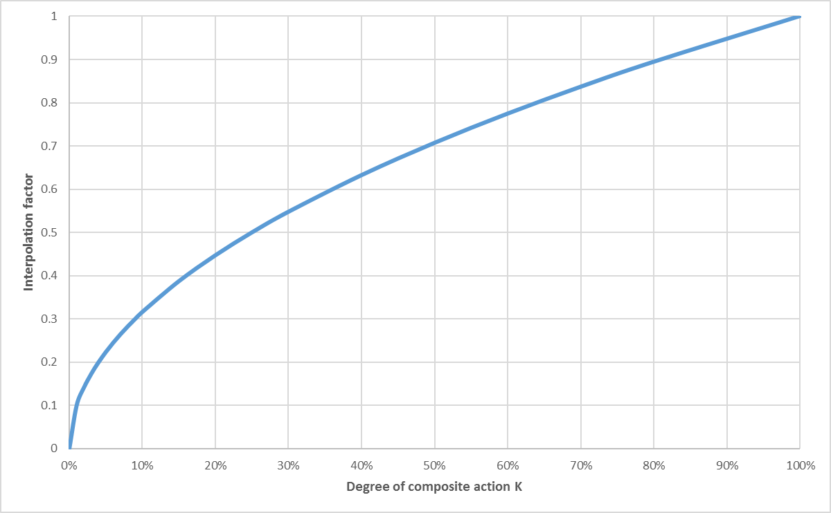
SCIA Engineer uses the square-root of the degree of composite action as interpolation factor, as proposed in AISC 360-10 (C-I3-4):

where
Icomposite = moment inertia of composite beam with partial composite action
Isteel = moment of inertia of steel beam
Ifull = moment of inertia of composite beam with full composite action
K = degree of composite action; 0 = no composite action; 1 = full composite action
In the context of composite structures, there are currently 3 possible types of behaviour for plate ribs in SCIA Engineer:
with standard composite action
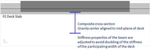
in this case, the composite beam is modelled as a plate rib without eccentricity. The shear connection may be total or partial. In order to consider the composite action, the stiffness of the beam is adjusted to take into account the effect of the eccentricity and of the participating deck width. In case the deck is taken into account as FE plate, internal forces for the composite checks are obtained by integrating the calculated stresses in both the steel beam and the deck.
This case applies directly the principle described above, with any value of K between 0 and 1. Common values of K for this case are, however, usually not taken lower than 0.25.
with advanced composite action
in this case, the composite beam is modelled as an eccentric plate rib (real eccentricity). This model is used only when the deck is modelled as a FE plate. When "advanced composite action" is selected and the linked 2D member is not a FE plate (e.g. a diaphragm), then "standard composite action" is used instead. Only a total shear connection is possible in this case. In this configuration, an axial force will appear in the beam and membrane forces will appear in the deck. The diffusion of the membrane forces in the deck (shear lag) will be automatically calculated by the FE model of the deck. The internal forces for the composite checks will be obtained by integrating the obtained stresses in both the steel beam and the deck (within the deck participating width).
This case does not use a transformed composite cross-section. The components of the composite system are modelled separately. As mentioned, only a full composite action is possible with this type of model. It is therefore not suitable for strength design with a partial composite action assumption. It is however particularly interesting in other cases, such as detailed floor vibration analysis (footfall).

without composite action
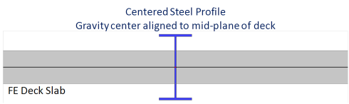
this is used to represent beams that are connected to the deck without shear connectors, i.e. the deck is just lying on the beam and may, in theory, slip on the beam. There is no composite action when using this option. This is modelled by a plate rib without eccentricity because the bending stiffness of such a beam is equal to the sum of the bending stiffness of the steel beam and the bending stiffness of the participating width of the deck. There is no lever arm effect of axial forces, as there would be in a beam with composite action.
This case is simply a particular application of the standard composite action case described above, using K = 0.
A beam without composite action is not a non-composite beam. It is a composite beam without composite action.
The pictures above show the analysis model used for composite beams, not the real structure.
The selected model for the deck (FE plate or diaphragm) affects the way the modified properties of the cross-section of the composite beams are determined. In the case of a diaphragm, the conventional approach applies mostly, as the stiffness of the deck is not taken into account directly by the analysis model in most cases. On the other hand, in the case of a FE plate, the stiffness values of the modified composite cross-section must be altered to avoid that the stiffness of the deck is taken into account twice.
Adjusted properties of beams “with standard composite action”
This section applies only to composite beams with standard composite action.
The stiffness values depend on the behaviour type of the 2D member the beam is attached to (see Element types).
| 2D member behaviour | Load panel | Standard FEM | Semi-rigid diaphragm | Flexible or rigid diaphragm | |
| Cross-
section properties |
A | Ab | Ab | Ab | Aadj2 |
| Ay | Ay,b | Ay,b | Ay,b | Ay,adj2 | |
| Az | Az,b | Az,b | Az,adj2 | Az,adj2 | |
| Ix | Ix,b | Ix,adj1 | Ix,adj2 | Ix,adj2 | |
| Iy | Iy,b | Iy,adj1 | Iy,adj2 | Iy,adj2 | |
| Iz | Iz,b | Iz,b | Iz,b | Iz,adj2 | |
A, Ay, Az, Ix, Iy, Iz = calculated stiffness components used in the analysis model
Ab, Ay,b, Az,b, Ix,b, Iy,b, Iz,b = nominal stiffness components of the steel beam without composite action, as listed in the cross-section properties in SCIA Engineer
Ix,adj1, Iy,adj1 = adjusted stiffness components of the composite beam, used in case the deck is modelled with Standard FEM behaviour
Aadj2, Ay,adj2, Az,adj2, Ix,adj2, Iy,adj2, Iz,adj2 = adjusted stiffness components of the composite beam, used in case the deck is modelled with Diaphragm behaviour (any type)
See below the detailed formulation of adjusted stiffness components. Please note, that for Standard FEM and Semi-rigid diaphragm, not all components are adjusted.
Deck data for a composite deck
This section applies only for composite decks. For metal decks, see next section.
In the following formulas, the following indexes apply:
All input orthotropic properties of the deck layers are detailed in the chapter Composite deck analysis model.
Average membrane stiffness of concrete and steel layers


d'n,mm are the orthotropic membrane properties of layer n in direction mm
Level of centre of gravity of the composite deck

zG,n is the level of the centre of gravity of layer n from the bottom fibre of the deck
Eccentricity of each layer from the centre of gravity of the composite deck


Combined orthotropic properties of the composite deck

D'c,jk, d'c,jk, D's,jk and d's,jk are the orthotropic properties of the composite deck layers;
D'd,jk and d'd,jk are the orthotropic properties of the composite deck.
Apply stiffness reduction factor for one-way deck


Deck data for metal deck
This section applies only for metal decks. For composite decks, see previous section.
Centre of gravity of the deck

Orthotropic properties of the deck

Rotation of orthotropic properties
In order to take into account the angle between the beam and the orientation of the sheeting.

where θ is the angle between the Y-LCS axis of the deck and the X-LCS axis of the beam.


Transformed properties of the deck
The properties of the participating width of the deck are transformed into equivalent cross-section geometric properties, related to the material of the beam.

Centre of gravity of the composite beam


Transformed properties of the theoretical composite beam


Final, adjusted properties of the composite beam
See summary table at the top of this chapter for exact usage of the following values.
K is the degree of composite action [0..1]
Adjusted properties for use with Standard FEM deck


Adjusted properties for use with diaphragms


