7 Internal forces
7.1 General
The internal forces, which are used for design reinforcement to 1D member can be different as internal forces calculated from FEM analysis. The differences may be caused by:
- Capping of moment and shear force for beams
- taken into account second order eccentricities (magnified moments)
Therefore, it is suitable to check values of internal forces, which will be taken into account for design and check. These forces can be checked in tree Concrete via service Internal forces.
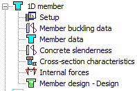
The service for check of internal forces is opened after clicking on the item Internal forces.
This service is standard 1D service where user can select:
- which members will be checked (properties Selection and Filters)
- for which loads case/combination/class the internal forces will be presented (properties Type of loads). The combinations and classes in this service are filtered according to selected Type of check.
- for which type of check the internal forces are presented. For ACI 318 code there is available only one item in combo box Type of check:
- Design ULS – the forces, which will be used for design of reinforcement to column will be presented. In this case only ULS combination, nonlinear combination with Type = Ultimate and classes without SLS combinations are available.
- if the explanation of errors and warnings, which are occurred during the evaluated of internal forces will be presented in numerical output (property Print explanation of errors and warnings)
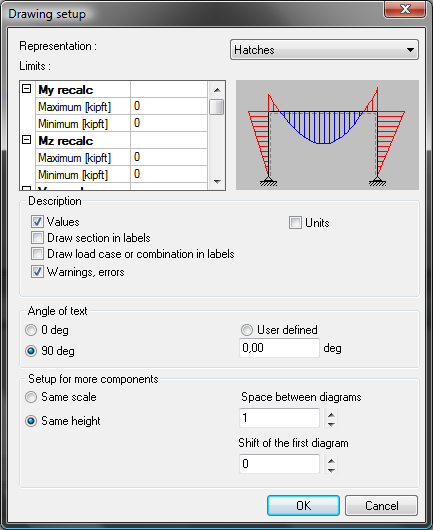
- how the values will be presented in graphical output (properties Drawing setup and Drawing)
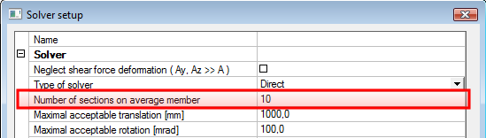
- positions, in which the numerical and graphical value will be evaluated (properties Extreme and Section). The number of section for evaluation of results depends on value Number of sections on average member in dialog Solver setup.
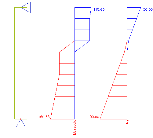
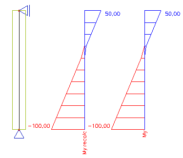
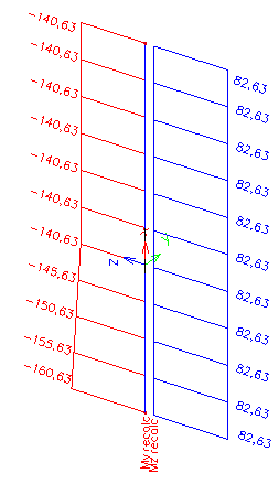
The recalculated bending moment My,recal and Mz,recal for the column will be different than standard bending moment from FEM analysis, only in case if check box Use buckling data is ON in concrete setup ( chapter "4.1 Concrete setup for 1D member" ) or in concrete member data (if concrete member data is inputted on the column, see chapter "5.2 Member data 1D (beams, beams as slab, columns)" ) and slenderness if bigger than lower limit slenderness
|
Use buckling data is ON |
Use buckling data is OFF |
|---|---|
|
|
|
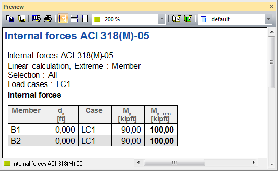
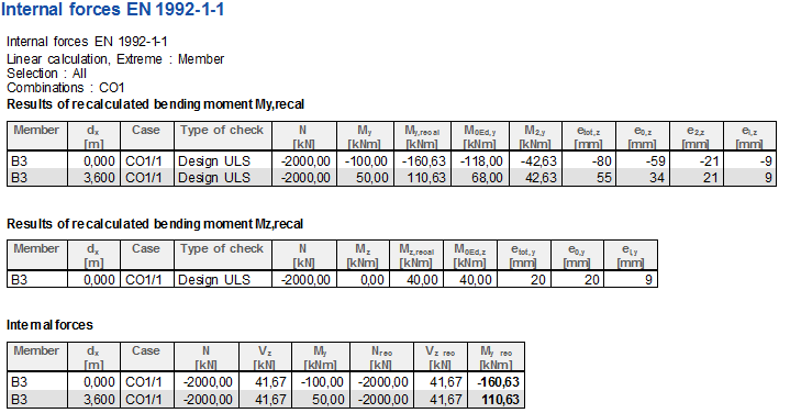
The numerical output is available after clicking on action button Preview. The numerical output depends on selected value in combo box Values:
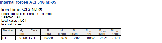
- for values N, My, Mz, Mx, Vz, Vz and Vz recall only one table is available, where are presented standard values from FEM analysis and recalculated bending moment My,recal and Mz,recal
- for values My recal and Mz recal and for columns there are two (only one values is selected) or three tables (both values are selected), where are presented detailed values, which were used for recalculation of internal forces (effect of slenderness.....)
Existing table can be edit via icon Table composer  or via double clicking on the header of the table.

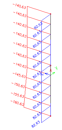
The values in graphical output are presented as follows:
- N and Mx are always presented in direction of x-axis of LCS
- Vy, Vz (Vz recal) are presented in direction of y(z)- axis of LCS
- My(z) and My(z),recall are presented about y(z) axis of LCS, it means perpendicular to y (z) axis of LCS
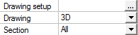
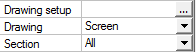
If the item More comp. is selected, then user can select if the values have to be presented in one plane (Drawing = Screen) or in direction (or about) of local axis (Drawing = 3D)
|
Drawing = 3D |
Drawing = Screen |
|---|---|
|
|
|
|
|
|
7.1.1 Property window
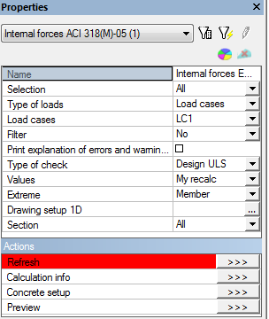
There are the following properties of the service
Name – Internal forces As ACI 318(M)-05; user is allowed to name the design. It might be very useful for better specification and orientation, especially in document.
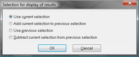
Selection – This attribute influences the total amount of members, which will be taken into the specific member design. There are four possibilities to be chosen from:
- All (all active 1D members will be designed)
- Current (only selected 1D members will be designed)
- Advanced (user may define the selection more specifically with relation to previous selection)
- Named selection (only 1D members from certain named selection, will be designed. new attribute “Named selection” will appear in the properties)
Type of loads – By this attribute user defines the type of the load for design generation. There are three possibilities to choose from:
- Combinations (user may choose from all combinations)
- Load cases (user may choose from all load cases)
- Class (user may choose from all result classes
In dependence on selected type of the load, new attribute Combination or Load cases or Class will appear right under this attribute. User may select desired Combination. Load case or Class from filtered list here.
Filter – It is possible to define filter for adjusting already selected type of selection. This will affect the number of 1D members taken into the design. User may select one from six possibilities:
- No (no filter will be applied)
- Wildcard (user may define the attributes for selection by himself)
- Cross-section (user may select specific cross-section only)
- Material (user may select specific material)
- Layer (user may select desired layer)
- Type of beam (user may define desired type of beam – beam or column)
Again, after selection one possibility a new appropriate attribute will be displayed right under, for further selection.
Print explanation of warning and errors – If this attribute is active, then table with all errors and warnings will be displayed in preview window. In fact two tables will be displayed. This is the same table as in Calculation info dialog.
Type of check – internal forces are different for each type of the check or design procedure. There is only design nonprestressed reinforcement in ULS for time being
Design ULS – internal forces used for design of nonprestressed reinforcement in ULS
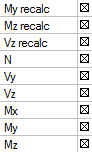
Values - By this attribute user may define the type of the value, he wants to be calculated and displayed. User may choose from drop down menu. Recalculated values are values used in selected type of check
- My recalc (recalculated bending moment around Y axis)
- Mz recalc (recalculated bending moment around Z axis)
- Vz recalc (recalculated shear force in Z direction)
- N – acting normal force
- Vy – acting shear force in Y direction
- Vz – acting shear force in Z direction
- Mx – acting torsional moment
- My – acting bending moment around Y axis
- Mz – acting bending moment around Z axis
Extreme - Simply said, this attribute defines what results to show in Preview window or document. User may choose from the following possibilities:
- Member – only elements with maximum results on each of selected 1D member will be displayed
- Section – results in each user defined or generated section will be displayed
- Interval – results with defined interval of values will be displayed
- Minimum – minimum value of results
- Maximum – maximum value of results
- Cross-section – maximum values for each cross-section will be displayed as results only
- Global – only elements with maximum results on selected 1D members will be displayed
Drawing setup – settings needed for proper displaying of the results
Drawing – option which enables to user different drawing in 3D window
Screen – selected values are drawn separately
3D – selected values are drawn using overlapping. User knows comparison between each other immediately
Section – when user selects as extreme type Section then there are the following option for sections
All – results for all sections will be displayed
Ends – results for end sections will be displayed only
Inputted – results for user defined sections will be displayed only
Inputted+Ends – results for user defined and end section will be displayed only
7.1.2 Action buttons
In the lower part of the Properties dialog are a few action buttons placed. User may find these buttons very useful.
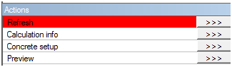
Refresh (this button is probably most important from all of them. It will start the process of design itself and it is needed to pres this button to refresh previous design results and to get new results, based on chosen attributes)
Calculation info (this button will open Calculation info dialog, where errors and warnings related to the design are displayed together with their description)
Concrete setup (see more info in chapter "4 Global setting " Concrete Setup action button)
Preview (this button will open Preview window with tables containing results of finished design, it might be also used for refreshing the results)